
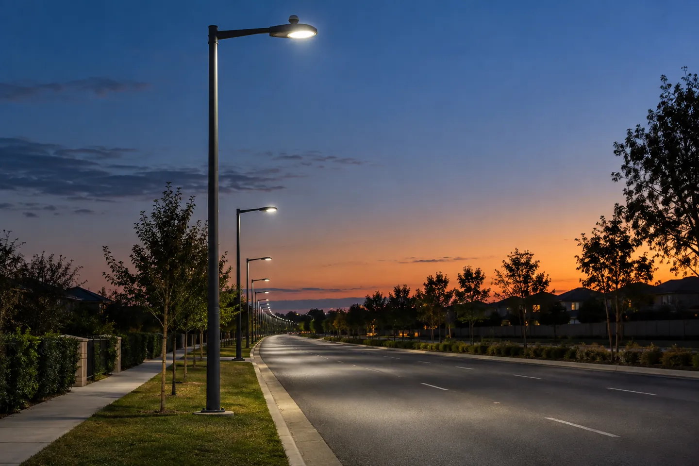
A street light that switches itself on at dusk looks unremarkable from the ground. The part doing that work, the photocell, is also the part most often mis-specified, mis-wired, and mis-blamed when something goes wrong. This guide walks the full distance: what the sensor actually does, which type fits which fixture, how the 3-pin, 5-pin and 7-pin NEMA interfaces differ, and what the failure modes look like when a whole run of poles starts cycling at midnight.
What a Street Light Photocell Is (and What It Isn’t)
A photocell is a small light sensor that turns a fixture on when ambient light drops below a set threshold and off when daylight returns. Most street light photocells use a light-dependent resistor (LDR): in darkness the resistance rises, the internal circuit trips a relay, and the lamp connects to power. At dawn the process reverses. The fixture is not running on a schedule; it is following the sky.
That distinction matters more than it sounds. A timer must be re-set as seasons change, while a photocell tracks sunset and sunrise automatically for the life of the installation. It also explains the short delay you may notice: manufacturers build a time lag into the switching so a passing windshield glare or a lightning flash doesn’t strobe the lamp. The sensor needs to see steady darkness (or steady daylight) before it commits.
One clarification while we are here, because the words get mixed constantly:
- A photocell responds to light levels (dusk-to-dawn switching).
- A motion sensor (PIR or radar) responds to movement: someone walks in, the light comes up.
- The small red blinking light on top of some street lights is a fault indicator, not either of the above.
This article is about the first one. Everything that follows builds on it: the shapes photocells come in, the standards that define their sockets, and the specific ways they fail in the field.
Photocell Types and Where Each One Fits
Photocells differ less by internals than by how they attach. Four form factors cover nearly every installation you will encounter.
Screw-in adapters thread into a standard lamp socket and sit between the bulb and the holder. They are the consumer workhorse: porch lights, barn lights, small yard posts. Whoever screws in a light bulb can install one, and replacement means unscrewing the whole unit.
Post-eye and junction-mounted units attach to the side of a pole or mounting plate with a small bracket. Electricians favor them for retrofits where the fixture itself has no provision for control, so the photocell sits in the supply line and switches the fixture from outside.
Swivel or fixed-mount photocells mount directly on the fixture body, usually with a short conduit connection. These are common on area lights and wall packs where the manufacturer expects daylight control but the fixture uses a hardwired entry.
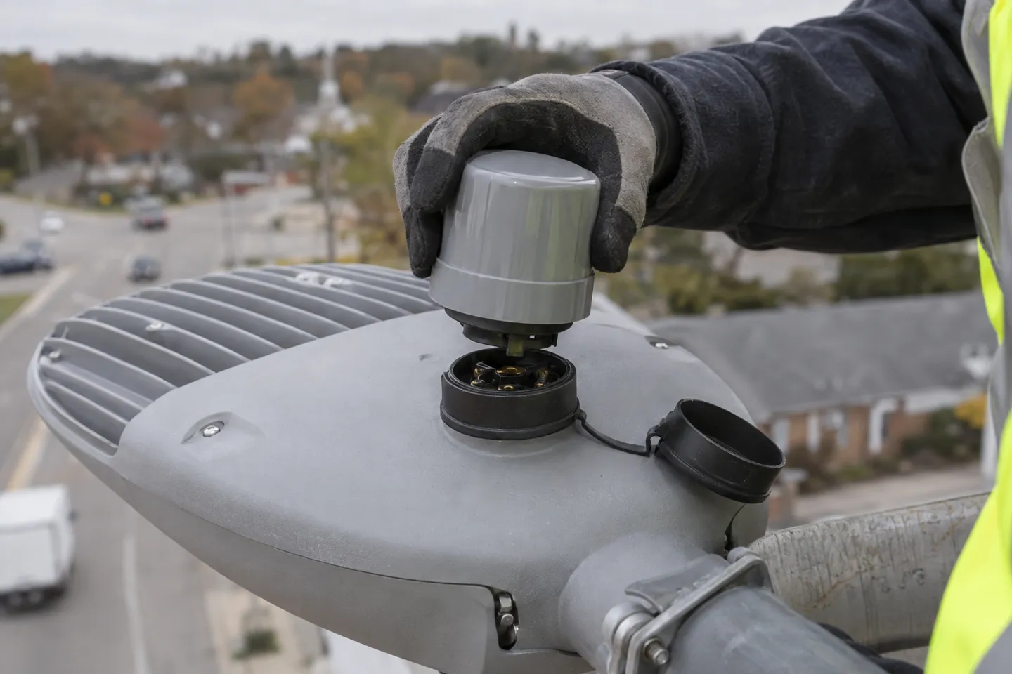
Twist-lock photocells plug into a NEMA receptacle built into the top or side of the fixture. Push, twist, done. The control becomes a consumable part: replace the cell without opening the fixture, without touching wiring, and (as we will see in the standards section) without even cutting power in many designs. This is the form factor that municipal and commercial street lighting has standardized on.
A quick self-check for your own fixture:
Does your fixture have a round 3-prong receptacle under a cap?
Twist-lock photocellDoes it have a standard screw socket?
Screw-in adapterIs it a pole or wall mount with exposed conduit?
Post-eye or swivel mountIs the fixture sealed with no provision at all?
Junction-mounted inline unitEach type carries its own weak point, and it is worth knowing before you buy. Screw-in adapters depend on the socket’s weather seal, so a cheap one becomes a water path. Twist-lock units are sealed well but rely on the receptacle gasket, which is why a failed gasket shows up as intermittent switching in wet weather. Mount the sensor so it faces the open sky, away from the fixture’s own light, a rule the failure section will come back to.
Photocell vs Timer vs Motion vs Smart Control
Choosing control is really choosing what the light should respond to: darkness, a clock, movement, or a network. Each answer fits a different site.
Four control strategies compared
| Control | Responds to | Wiring & setup | Season behavior | Best fit | Where it struggles |
|---|---|---|---|---|---|
| Photocell | Ambient light level | Minimal — inline or twist-lock | Tracks sunset/sunrise automatically | Streets, parking lots, any “dark means on” site | Indoor or shaded light, extreme latitudes |
| Timer | A clock schedule | Set switching times by hand | Needs seasonal adjustment | Fixed schedules, decorative hours | Any site where dusk time shifts matters |
| Motion sensor (PIR/radar) | Movement | Sensor aiming and range tuning | Season-neutral | Security perimeters, pathways with sparse traffic | Continuous-occupancy roads (constant triggering) |
| Smart control (Zigbee/LoRaWAN) | A network command — schedules, dimming, telemetry | Controller per pole plus network gateway | Fully programmable | City-scale fleets, adaptive dimming, monitoring | Sites without network coverage or maintenance budget |
For a straightforward “dark means on” site, the photocell wins on simplicity and cost: no programming, no calendar drift, nothing to relearn after a power outage. Timers still make sense where lighting must follow fixed hours regardless of sky, as with a sign that must extinguish at 23:00. Motion sensors solve a different problem (light only when someone is there) and pair naturally with photocells on pathways. Smart control sits at the top of the stack: dimming schedules, per-pole monitoring, fault reporting.
Here is the trend worth your attention, because it is already written into procurement documents. Municipal bids increasingly demand not just photocell control but a future path to networked control on the same fixture. The City of Ellsworth, Maine, for example, requires in its August 2025 streetlight proposal that each luminaire be “controls ready” utilizing the ANSI C136.41 photocell receptacle, with dimmable drivers, explicitly so the city can add smart controls at installation or years later (City of Ellsworth, 2025).
Written into a 2025 municipal bid — City of Ellsworth, Maine
“We require each luminaire to be ‘controls ready’ utilizing the ANSI C136.41 photocell receptacle.”
The socket itself is now a specification line, not an accessory.
Read that twice: the deciding line in the bid is not which control technology wins, it is whether the fixture’s interface can accept tomorrow’s control without replacing the luminaire. That reframes the whole selection order (interface first, control technology second) and it is exactly where pin counts and standards come in.
Send WOSEN your site type and driver specs, and our engineers will map the right 3/5/7-pin configuration for your project within 12 hours.
Get a configuration reviewPin Counts and Standards: Specifying the Photocell Interface
Three numbers dominate street light control specs: 3-pin, 5-pin, 7-pin. They sound like capacity ratings. They are not. They are capability tiers on the same physical socket.
Same base, three abilities
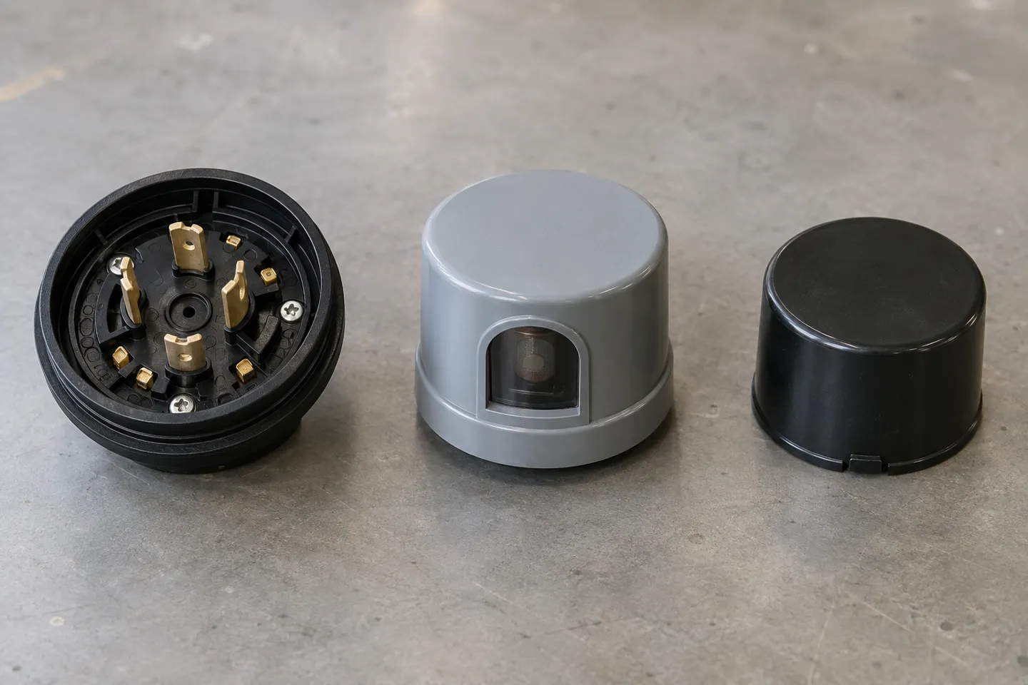
All three use the same three-prong twist-lock power connection, which is why a photocell, a shorting cap, and a smart module can physically interchange on one receptacle (LED Light Expert, 2021). What changes is what the extra contacts carry:
3-pin vs 5-pin vs 7-pin at a glance
| Configuration | Standard | Contacts | What it carries | Typical role |
|---|---|---|---|---|
| 3-pin | ANSI C136.10 | 3 power (line, load, neutral) | On/off switching only | Basic dusk-to-dawn photocell, shorting cap |
| 5-pin | ANSI C136.41 | 3 power + 2 dimming | 0-10V dimming pair | Photocell or module that can dim the driver |
| 7-pin | ANSI C136.41 | 3 power + 4 additional | Two dimming pairs or dimming + low-voltage communication | Networked smart controls, monitoring modules |
The dimming contacts are the point of the 5- and 7-pin versions. TE Connectivity’s ANSI C136.41-2013 receptacles, for instance, provide two or four dimming contacts supporting 0-10 VDC or DALI dimming alongside the three twist-lock power contacts (TE Connectivity, 2013). The shorting cap deserves its own sentence: it is a twist-lock plug with no electronics at all, internally jumping line to load, used to bypass control on a fixture that must stay constantly on or that will be controlled elsewhere in the circuit (LED Light Expert, 2021).
Electrical matching: the hidden trap
The socket is standardized; the electrical fit is not automatic. Three checks belong in every spec before you sign off a control:
- Voltage class. Most NEMA photocells are rated 120–277 V and cover the vast majority of commercial installations; 480 V circuits need controls rated for that class. Confirm the fixture’s driver input range against the control’s rating rather than assuming.
- Load capacity in the LED era. Older photocell designs were rated for the high-wattage loads of HID lighting; legacy datasheets carry ratings of 800–1000 W tungsten/ballast. An LED street light drawing 30–100 W sits far below those numbers, and with some electromechanical designs a very low load can cause chattering or poor relay behavior. LED-rated photocontrols exist precisely for this; check the manufacturer’s stated load range and minimum load on the datasheet rather than carrying over an HID-era part number.
- Driver dimming interface. A 5- or 7-pin control can only dim a driver that has a 0-10V (or DALI) input. The receptacle without a compatible driver is a road to nowhere. Verify the driver spec first, then the socket.
Factory-installed vs retrofit
There are two ways a fixture ends up photocell-controlled, and the difference shows up in your maintenance budget. A factory-installed receptacle comes sealed, gasketed, and wired to the driver by the manufacturer; the control ships separately (or as a shorting cap) and twists in at commissioning. A retrofit adds an inline or post-mounted photocell to a fixture that never had provision, which is viable but introduces its own cable entries, its own seals, and its own failure points in exactly the environment (moisture, temperature swing) where photocells are most fragile.
For new procurement the specification line to write is the interface, not the brand: “twist-lock receptacle per ANSI C136.10” for on/off photocell control, or “ANSI C136.41 dimming receptacle, 7-pin, controls-ready” where networked control is the destination. One boundary note for readers outside North America: Europe’s smart street lighting increasingly rides the Zhaga Book 18 interface instead. Same concept (standardized control socket), different geometry, so a US-specified NEMA receptacle will not accept a Zhaga controller or vice versa.
How do these configurations map onto real sites? Use this matrix:
Site × configuration × boundary: what to specify and when it stops working
| Site | Recommended configuration | Switch to this when | Boundary — fails or wastes money if |
|---|---|---|---|
| Private yard / porch | Screw-in adapter on the fixture | Post-eye unit if socket is weathered | Adapter seal degrades → water path into socket |
| Barn / alley / small lot | Post-eye or swivel-mount photocell | Add contactor for circuits above control’s load rating | Severe cold embrittles seals — check temperature rating |
| Parking lot / campus roadway | 3-pin (C136.10) twist-lock photocell | 5-pin if driver has 0-10V input and dimming schedules are wanted | Photocell placement under tree canopy or signage → false switching at night |
| Municipal street / highway | 7-pin (C136.41) factory-installed, controls-ready + shorting cap at delivery | Add photocell module for on/off now, networked module later | Regions adopting Zhaga Book 18 — NEMA receptacle will not accept those controllers |
| Smart city retrofit program | 7-pin + networked control module (Zigbee/LoRaWAN/NB-IoT) | Stage deployment: shorting cap first, modules by district | Areas without network coverage — modules lose uplink, fall back to local schedule |
When Photocells Fail: Field Diagnosis and Acceptance Tests
Almost every photocell complaint collapses into one of three symptom groups, and each group points to different causes. Diagnose in the order below; it is arranged so the cheapest check comes first.
Three symptom groups
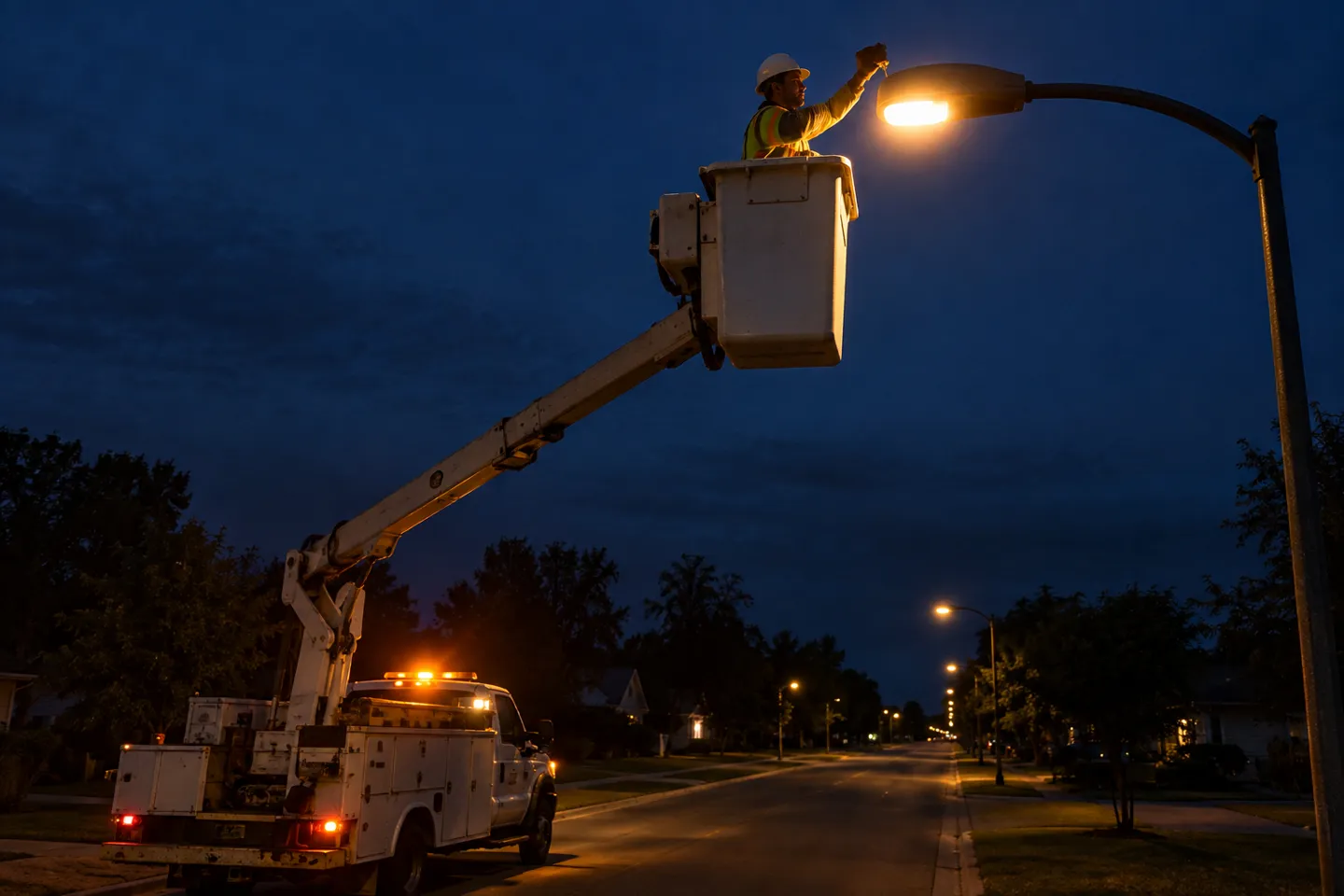
Stays off at night usually means the sensor never sees darkness. An upstream street light or building floodlight is hitting it, the window is dirty or snow-capped, or the cell’s internal relay has welded open from years of switching. Stays on in daytime is the mirror image: the sensor cannot see daylight, or the relay has welded closed. Cycles on and off is the group that fills forums, and it is the most instructive, because cycling means the sensor is working but its view of the world keeps changing.
The cycling diagnosis, in order
Electricians have a folk rule, “a blinking photocell light is wired backwards,” and it is sometimes true, which is exactly why it is dangerous as a first guess. Run the sequence instead:
Cover test: tape a dark cover over the sensor window for 60–90 seconds. If the light settles, the electronics and wiring are fine — the problem is what the sensor sees, not what it is.
Look at what the sensor sees: is it mounted where the fixture’s own light, a neighboring pole, or reflective cladding reaches it? A photocell that can see its own lamp will switch the lamp off, see darkness, switch it back on — the classic midnight cycling loop documented by installers (Mike Holt’s Forum, 2013).
Verify wiring: load and line swapped on a 3-pin installation produces exactly this behavior. The folk rule belongs here — third in the sequence, not first.
Check the part and the batch: a PIR motion unit supplied by mistake will behave like a cycling photocell; so will an LED-rated control driven below its minimum load; so will a batch of aging cells — facility crews report whole runs of poles blinking in the same season when one production batch ages out together.
Check supply voltage: drivers and photocontrols both misbehave near their voltage limits, and chronically high or low feed mimics control failure.
“Blinking = wired backwards” is true often enough to cost you a correct diagnosis. It is one of four common cycling causes — cover-test the sensor before re-terminating any wiring.
The occlusion failure deserves a note of respect: maintenance electricians tell stories of a parked forklift or a season’s worth of bird nesting shading one sensor and knocking a whole circuit into confusion. Photocells are honest devices; they report exactly the light they receive, which is not always the light you intended them to receive.
Acceptance tests and warranty language
If you are accepting a shipment or commissioning an installation, three checks catch most of the above before the poles are energized for a season. First, a bench switching test: cover and expose each photocell and confirm clean on/off transitions with the specified delay, no chatter. Second, a seal inspection: receptacle gasket seated, sensor window unscratched, twist-lock action positive. Third, a paperwork check: the control’s voltage class and load range against the fixture’s driver and, if the fixture is controls-ready, confirmation of which standard the receptacle follows (C136.10 on/off, C136.41 dimming). Warranty language should say explicitly whether the photocell and receptacle gasket are covered items and for how long. They are the two parts of the control path that live outdoors at the mercy of UV and thermal cycling, and they are the two most likely to need replacement within the fixture’s life.
What This Means for Your Lighting Line or Bid
Strip the detail away and three judgments remain, all resting on facts already established above.
First, specify the interface as a product-line default, not an option. The 3-pin, 5-pin and 7-pin controls all ride the same twist-lock base, and procurement documents like Ellsworth’s already demand controls-ready receptacles by name. A street light line that ships with a C136.41 receptacle and shorting caps covers the photocell bid today and the networked-control bid tomorrow with a module swap. One structural decision, two bid categories.
Second, let the failure modes write your acceptance clauses. The cycling diagnosis sequence and the bench switching test above are exactly the clauses that keep a container of controls from becoming a season of midnight service calls. Write the cover test, the seal inspection and the voltage/load verification into your incoming inspection, and state which control parts carry warranty coverage.
Third, keep standards in the spec and brand names out. The receptacle standard outlives any single control module. Write ANSI C136.10 or C136.41 into tender documents and treat the control itself as the consumable it is.
That is also how we build our own line at WOSEN. Our LED street light series ships with factory-installed NEMA 3/5/7-pin receptacles and supports Zigbee, IoT and LoRaWAN smart modules on the same base, the upgrade path described above, ready at the factory rather than retrofitted in the field (LED street light series). We back the street lighting lines with warranties of up to 5–7 years and answer international inquiries within 12 hours. A control-ready fixture is only as good as the support behind its warranty.
If you are comparing suppliers for a controls-ready street light line, our certifications (UL, ETL, TUV, ENEC, SAA and ISO 9001) and full specifications are available on WOSEN’s site.
Make your next street light bid controls-ready
Factory-installed NEMA 3/5/7-pin receptacles, shorting caps on request, and Zigbee / LoRaWAN smart modules on the same base — backed by 5–7 year warranties and 12-hour inquiry response.
Start a controls-ready inquiryReferences
- City of Ellsworth, Maine. “LED Streetlight Proposal (RTE), August 21, 2025.” 2025. https://www.ellsworthmaine.gov/wp-content/uploads/2025/09/RTE-Energy-Proposal.pdf
- TE Connectivity. “LUMAWISE Endurance N Dimming Receptacles (ANSI C136.41).” https://www.te.com/en/products/connectors/lighting-connectors/street-lighting-controls/ansi-street-lighting-receptacles.html
- LED Light Expert. “Photocell Receptacles: 3, 5, or 7 Pin NEMA Standards.” 2021. https://ledlightexpert.com/photocell-receptacles-3-5-or-7-pin-nema
- Mike Holt’s Forum. “LED street lights going on then off.” 2013. https://forums.mikeholt.com/threads/led-street-lights-going-on-then-off.104579
- WOSEN. “LED Street Lights.” https://www.wosenled.com/outdoor-lights/led-street-lights/
- WOSEN. “WOSEN: Leading LED Lighting Manufacturer Since 1992.” https://www.wosenled.com/

 English
  Spanish
  French
  German
  Italian
  Arabic
  Russian
  Portuguese
  Dutch
Dutch  Indonesian
  Turkish
  Polish