
A 20,000 sq ft warehouse at 26 ft rarely fails on lumens. It fails on the floor: fixtures spaced exactly as a catalog chart suggested, a dark seam running down the middle of the picking aisle, and a retrofit quote for six extra mounting points that nobody budgeted. High bay light spacing is the decision that produces that outcome, long before the first fixture is hung.
Spacing decides three things at once: how evenly the floor is lit, how many fixtures and circuits you buy, and how easy the installation is to reach and maintain for the next decade. Get it right and the layout passes inspection on the first walkthrough. Get it wrong and the corrections happen with a lift rental and a crew on site.
This article treats spacing as a decision chain rather than a single number: start from the rule-of-thumb ratios, correct for your actual fixture and target light level, adapt the grid to the real geometry of the floor, and then verify the result at the level your project demands. Most guides stop at step one. The steps after it are where layouts are won or reworked.

What High Bay Light Spacing Actually Decides
High bays are fixtures designed for mounting heights of roughly 15 to 20 ft (4.5 to 6 m) and above. Below that line you are in low bay territory, where a wider beam spreads light evenly across a shallow room. The distinction matters because a low bay throws light broadly while a high bay throws it down narrowly, and the two respond to spacing in opposite ways.
Before going further, measure the mounting height, not the ceiling height. A pendant-mounted fixture hangs 2 to 3 ft below the slab, and every ratio in this article keys off that lower number. If your mounting height comes out under about 15 ft, the ratios below will over-space your fixtures and this article’s method needs a low bay approach instead.
Two adjacent topics stay out of scope here. Residential recessed can spacing follows its own rules tied to trim size, and low bay layouts deserve their own treatment. What remains, from a garage workshop at 12 ft to a distribution center at 40 ft, is one continuous problem: place points of light on a plane so that the work surface below stays evenly lit.
That problem has a natural order. You start with a ratio, correct it for the fixture you actually plan to buy, bend the grid around racks and aisles, and then prove the result. Each step has its own logic, and the next section starts where everyone starts: the ratio.
The Rule-of-Thumb Ratios, and Why They Disagree
Ask how far apart high bay lights should be and you will collect answers with real spread between them. One guide sets spacing at 1 to 1.5 times the mounting height (LEDLightingExpert, 2025). Another divides ceiling height by two (PACLights). A third recommends 0.8 to 1.2 times mounting height as the working baseline for most fixtures (ELEDLights).
Six published spacing ratios span 0.5× to 1.5× mounting height.
At a 30 ft ceiling, that is the difference between spacing fixtures 15 ft apart and 45 ft apart.
The ratio is not the answer; it is a default that assumes a fixture you have not chosen yet.
The disagreement is not mostly error. Each ratio compresses a different set of assumptions: a lumen package, a beam angle, a target light level. A 90° optic at 20,000 lumens over bulk storage tolerates wide spacing. A 60° optic over workbenches does not, no matter what the chart says. The chart was never written for your fixture.
With that caveat, the workable baseline for most LED high bays sits between 0.8 and 1.2 times mounting height, which matches the spacing-to-mounting-height ratio (S/MH) concept used in photometric practice, defined as the distance between fixture centers divided by the mounting height (IES). Use the low end with narrow optics or demanding light levels, the high end with wide optics over storage. The table below translates that into numbers, in both feet and meters since project drawings use either.
High bay spacing by mounting height (0.8× to 1.2× baseline)
| Mounting height | Conservative end (0.8×) | Wide end (1.2×) |
|---|---|---|
| 15 ft (4.6 m) | 12 ft (3.7 m) | 18 ft (5.5 m) |
| 20 ft (6.1 m) | 16 ft (4.9 m) | 24 ft (7.3 m) |
| 25 ft (7.6 m) | 20 ft (6.1 m) | 30 ft (9.1 m) |
| 30 ft (9.1 m) | 24 ft (7.3 m) | 36 ft (11.0 m) |
Two fixture-form notes complete the map. UFO-style round high bays and linear high bays distribute light differently: a linear fixture stretches its beam along the row, so the same ratio buys more spacing along the row axis than across it. And if you came here holding a chart from a specific brand, treat its numbers as describing that brand’s default optic and lumen package. Which raises the fair question: when your fixture and target differ from the chart’s assumptions, which way does spacing move? Three variables decide that.
The Three Variables That Move Your Spacing
The ratio gives you a range; three variables tell you where in the range your project lives. Here is the short version before the detail:
The three spacing variables at a glance
| Variable | What it moves | Direction | Failure when ignored |
|---|---|---|---|
| Beam angle | Coverage per fixture | Narrower optic allows wider spacing but raises dark-spot risk | Dark bands between fixture rows |
| Lumens and target light level | Number of fixtures needed | Higher lumens or lower fc target allows wider spacing | Over-lit or under-lit floor |
| Mounting height | The ratio itself | Higher mounting stretches every distance proportionally | Chart read at the wrong height |
Beam Angle Sets the Ceiling on Spacing
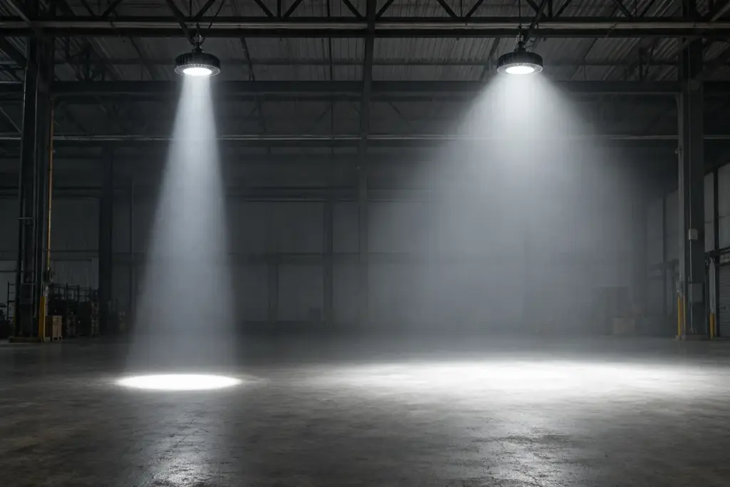
Beam angle decides how much floor one fixture can cover. A 60° optic concentrates light in a tight cone: bright directly under the fixture, dim quickly beyond it. A 120° optic spreads the same lumens across a much wider circle. That geometry explains why “beam angle changes everything”. A coverage circle grows with both the angle and the mounting height. So a narrow optic hung high still covers a wide circle, while the same optic at low height cannot.
The practical rule: narrow optics buy spacing width at the cost of overlap, and overlap is what hides dark seams. Space 60° optics at 1.2 times mounting height over a workbench area and you will see it in the floor: bright discs under fixtures, shadow between them. Wide optics at tight spacing overlap generously and forgive layout errors. As a working position, wide beams over general storage can run toward the wide end of the ratio. Narrow beams belong over tall aisles or high mounting positions, where their throw is an asset. Everywhere else they demand tighter verification.

Lumens and Target Light Level Set the Count
The second variable pair works through quantity. Target light levels for industrial spaces follow published ranges attributed to the IES: general storage sits around 5 to 20 fc (50 to 200 lx), active warehouse areas with fine picking run 20 to 50 fc (215 to 538 lx), and workshop or assembly work sits around 30 to 75 fc (300 to 750 lx) (Ledvance).
The interaction is simple once stated. A 33,000-lumen fixture spaced like a 15,000-lumen fixture over the same target doubles the light on the floor; halve the lumens and keep the spacing and you halve the result. Higher target light levels (assembly, inspection) pull spacing tighter at any given lumen package. This is why charts written for “a high bay” mislead: they bake in one lumen-and-target pairing and go quiet about the rest.
The Lumen-Method Cross-Check
Before committing to a grid, run the count backwards from the target. The lumen method estimates fixture count from the area and the light target: fixtures = (area × target fc) ÷ (lumens per fixture × utilization factor × maintenance factor). The utilization factor, typically around 0.8 for a clean industrial room, accounts for how much of each fixture’s output actually lands on the work plane; the maintenance factor, around 0.85, reserves output for the lumen depreciation and dirt of the years between cleanings.
A worked example: the 20,000 sq ft bay from the opening, targeting 20 fc for active storage, using 24,000-lumen fixtures. The count runs (20,000 × 20) ÷ (24,000 × 0.8 × 0.85) = 400,000 ÷ 16,320, or about 24.5, so 25 fixtures. On a 200 × 100 ft floor that grids out to roughly seven rows of three to four fixtures, spacing near 28 ft against a 26 ft mounting height. The S/MH ratio lands at 1.1, inside the baseline band, which tells you the count and the ratio agree.
Worked example
20,000 sq ft, 20 fc target, 24,000 lm fixtures, UF 0.8, MF 0.85. Count = 400,000 ÷ 16,320 ≈ 25 fixtures. Grid on a 200 × 100 ft floor ≈ 28 ft spacing at 26 ft mounting, S/MH ≈ 1.1. Count and ratio cross-checked.
Know what the cross-check does not do: it verifies the average, not the uniformity. Twenty-five fixtures can average exactly 20 fc and still leave a dark lane where the grid and the racks disagree. Averaging is arithmetic; uniformity is geometry, and geometry is the next station.

Laying Out the Floor: Open Bays, Racking Aisles, and Access
Open-Floor Grids: Where the Ratio Works
In an open bay without racking, the ratio grid survives contact with reality. Rows run parallel to the building’s long axis, fixture positions avoid ceiling fans, crane rails and duct runs, and the perimeter row sits about half a spacing from the walls. The half-spacing rule is not aesthetics: each fixture’s coverage circle extends roughly half a spacing beyond the last row, so pulling the perimeter row in keeps the wall line from going dim.
Racking Aisles: Why the Grid Breaks
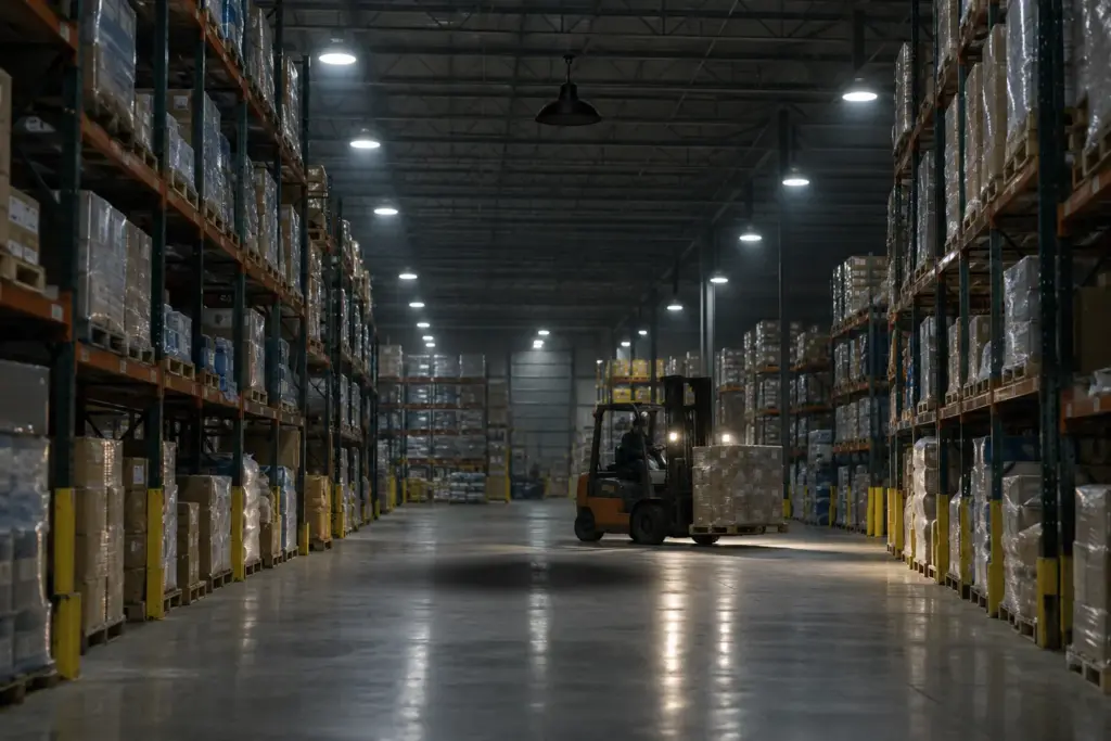
Racking changes the problem. A uniform grid drawn over a rack building puts fixtures where the racks happen to be, and light that lands on the top of a rack stack lights cardboard, not work. Fixture rows belong on the aisle lines, not on a grid independent of them, and narrow aisles under about 12 ft (3.6 m) want narrow or aisle-specific optics that throw lengthwise down the aisle.

The failure mode is on record. Electricians retrofitting a 35 ft document-storage warehouse found the existing HID high bays sitting over the rack tops rather than the aisles (Mike Holt’s Forum, 2007). Light was landing on storage while the 30-inch walkways between the racks stayed dim. The poster’s own words describe the building as very dark. Fixture count was never the problem; positions were. Every one had to be re-worked at 30-plus feet, with access equipment that barely fit the aisles.
Field record
35 ft document warehouse. HID fixtures sat over the rack tops; the pick aisles stayed dark.
30 in walkways. No standard lift fit between the racks; every fixture came down for re-work at height.
Mounting and Maintenance Access
Spacing is also a maintenance decision. Every additional fixture is an additional point that someone reaches with a lift for the next twenty years, so over-tight spacing buys uniformity at a cost paid annually. Conversely, the retrofit above shows the opposite corner: positions that cannot be reached at all, in aisles too narrow for standard scissor lifts. Layout that ignores access equipment produces fixtures nobody can service. Crews hanging fixtures on suspended cable level them with lasers for a reason; set positions that respect both the light and the ladder.
Fixture selection is the other half of access. If your layout has aisles like these, ask for optics before you ask for a price. Our LED high bay lights (WOSEN) are offered with beam angles from 15° to 120°, with dimming standard across the series and drivers upgradeable to Meanwell, Inventronics or Philips where the specification demands; the series pages list a 5-year warranty. CE and RoHS ship as standard, and UL, ETL, SAA, ENEC or TUV marks can be arranged for the destination market. Voltage versions are not published on the product pages, so we confirm them at quotation. Narrow aisles, tall racks, cold stores: send the rack height and the aisle width first, and we match the optic and the mounting to the access you actually have.
The matrix below condenses the section into a site checklist. Walk the floor once, confirm the “check first” column, and the grid you draw will survive the walkthrough.
Layout strategy by floor scenario
| Scenario | Layout strategy | Ratio applicability | Where it breaks | Confirm first |
|---|---|---|---|---|
| Open bulk storage | Uniform grid, perimeter at half spacing | Works as baseline | Obstructions: fans, crane rails, ducts | Mounting height vs ceiling height |
| Narrow racking aisles under ~12 ft | Fixture rows on aisle lines, narrow or aisle optics | Grid ratio fails | Light lands on rack tops, aisles stay dim | Aisle width, rack height, optic options |
| Assembly or fine-work zones | Tightened grid to a higher fc target | Ratio alone under-lights | Average meets target, uniformity fails | fc target per task, uniformity spec |
| Perimeters, docks, walkways | Fixtures follow traffic lines, not the grid | Not a ratio question | Lit floor nobody walks | Traffic pattern, door positions |
What to Ask a High Bay Supplier Before You Commit
The method so far depends entirely on documents the supplier either has or does not have, which makes the supplier question concrete rather than promotional. First, photometric files: a real IES file for each optic and lumen package, not a datasheet drawing. Every check you run later depends on that file. Second, the spacing criterion (SC) value from the photometric report, which tells you the maximum spacing the fixture itself supports for acceptable uniformity.
Third, configuration: beam angle options, dimming protocol, sensor compatibility, and whether drivers come from named manufacturers or “equivalent”. Fourth, the paper: warranty length in the contract rather than the brochure, plus written confirmation of certifications for your destination market. “Available on request” and “held” are different inventory positions, and only one of them clears customs on your schedule. Fifth, the boring one that strands projects: the input voltage version. Many manufacturers do not publish voltage ranges on product pages, and a fixture that cannot accept your supply voltage is a reorder, not a discount.
Price the request accordingly. A supplier who answers all five items in one email is telling you something about how the project will run after the wire transfer. A supplier who answers with a catalog chart is telling you something too.
Send your drawings and target light levels to WOSEN, and the five answers come back with the quotation.
Send Your Project to WOSENFrom Rule of Thumb to Photometric Proof
Verification comes in three levels, and choosing the right level is itself a decision.
Level 1: Rule-of-thumb grid. Ratio times mounting height, adjusted by beam angle. Sufficient for open bays, low targets, and early budgeting.
Level 2: Lumen-method count. Area times target fc over delivered lumens, cross-checked against the grid. Sufficient for standard storage and workshop pricing.
Level 3: Photometric simulation. The layout rendered in software with the supplier’s IES files, reporting uniformity and point values across the actual rack geometry. Required for racking layouts, mixed zones, and any project with an acceptance clause.
The boundary between levels follows project risk. A 5,000 sq ft shop with open floor and a forgiving target stops at level two. A rack building, a mixed floor with assembly cells, or any project with a signed lighting specification requires level three. The average is what the lumen method verifies; it is not the quantity the acceptance walkthrough measures.
That quantity is uniformity: the minimum-to-average ratio across the task area. European practice codifies it directly. EN 12464-1 requires illuminance uniformity of Uo ≥ 0.40 in the immediate surrounding area of work tasks, or across the whole area when the task location is not yet fixed (Performance in Lighting). Rack storage adds a second axis. Picking needs vertical illuminance on the rack faces, not just horizontal light on the floor. A grid that verifies only horizontal values can pass on paper while the labels stay in shadow.
The simulation report then earns its keep twice. It goes into the tender or handover file as evidence the design meets its numbers, and it settles the later argument about whether a dark aisle is a design defect or an expectation gap. Which points back to the supplier question: the report is only as honest as the IES files underneath it.
What This Means for Your Lighting Business
Read back through this chain and the commercial pattern is hard to miss. Six public ratios disagreeing by a factor of three means a quote that says “standard spacing” carries no information. A quote built on the client’s rack layout and mounting height carries an evening of work and no competition. The contractor who walks the floor, counts fixtures from the lumen method, and delivers a photometric report is selling certainty in a market selling boxes.
The rework economics point the same direction. Aisle-top fixtures and over-spaced rows are corrected with lift rentals, crew days and schedule slip, all after the invoice. Layout capability is therefore a margin item, not an overhead. And acceptance increasingly runs on uniformity and photometric documents. The supplier who can produce IES files, optic options and layout support turns that verification burden into a deliverable you can resell.
So invert the usual inquiry. Ask for IES files, SC values, beam angle and dimming options, warranty terms and voltage confirmation before asking for unit price, and weight your stocking toward fixtures that configure: narrow optics for aisles, dimming for zones. The fixture price was never where this project was won.
Get a Layout, Not Just a Fixture Count
Send WOSEN your bay dimensions, rack layout and target light level. The quotation comes back with IES files, optic options and a count you can defend at the walkthrough.
Request a Layout QuoteReferences
- Illuminating Engineering Society. “Spacing-to-Mounting-Height Ratio, S/MH.” IES Lighting Library. https://ies.org/definitions/spacing-to-mounting-height-ratio-s-mh/
- Mike Holt’s Forum. “Hi-Bay Lighting.” 2007. https://forums.mikeholt.com/threads/hi-bay-lighting.34549/

 English
 Spanish
 French
 German
 Italian
 Arabic
 Russian
 Portuguese
 Dutch
 Indonesian
 Turkish
 Polish