Specify the wrong beam angle, and your commercial lighting project faces catastrophic dark spots, blinding glare, or failed compliance inspections. This engineering-grade guide provides the exact parameters, spacing formulas, and photometric rules to get your ceiling lighting right the first time, ensuring your facility meets strict professional standards without costly rework.
Understanding Beam Angle Basics
Before diving into height matrices and complex spacing calculations, we must strip away the common amateur misconception that a beam angle is simply “how wide the light looks on the floor.” In commercial and industrial engineering, it is a strictly defined photometric boundary that dictates light distribution, human visual comfort, and overall energy efficiency. Relying on visual guesswork or assuming all wide-angle fixtures are identical will inevitably lead to systemic project failure.
FWHM: The True Definition of a Beam Edge
According to the authoritative testing standards set by the Illuminating Engineering Society (IES), the beam angle of any commercial luminaire is officially defined by the Full Width at Half Maximum (FWHM). This is a non-negotiable metric in professional lighting design that separates consumer-grade bulbs from engineering-grade fixtures.
To understand this practically, imagine a high-pressure water nozzle. The most pressurized, effective water stream is concentrated in the absolute center, while a lighter mist sprays outward from the sides. If you are trying to strip paint off a wall, only the high-pressure center actually does the work. In architectural lighting, the beam angle only measures the central geometric cone where the light intensity (measured in Candelas) remains at 50% or more of its peak center value.
When a manufacturer states a fixture has a 40° beam angle, they are mathematically guaranteeing that the highest quality, most intense, and functionally usable light is strictly contained within that specific 40-degree cone. Any light scattered outside of this boundary is not factored into the primary illuminance calculation for your working plane.
Beam Angle vs. Field Angle
If the Beam Angle is the 50% intensity drop-off point, what happens to the rest of the light? Does it simply disappear? This brings us to a critical, often-overlooked metric: the Field Angle. The field angle is the definitive boundary where the light intensity drops to exactly 10% of the peak center value.
Understanding the difference between these two parameters is the secret to high-end, glare-free lighting design. Consider a high-end retail jewelry store or a museum exhibit. If you only look at the 50% beam angle to highlight a diamond display, you might assume you have the perfect spotlight. However, if the fixture utilizes poorly controlled optics and possesses a massive 10% field angle, it will produce uncontrolled “spill light.” This spill light bleeds indiscriminately into the surrounding shadows, washing out the visual contrast, flattening the texture of the merchandise, and completely destroying the dramatic focal point you intended to create. True optical precision requires a manufacturer capable of managing both boundaries simultaneously.
The Master Beam Angle Selection Matrix (The Two-Step Protocol)
A fatal, yet incredibly common, mistake in commercial lighting procurement is choosing an angle based solely on the name of the room. A “warehouse” does not automatically dictate one specific fixture type, because a warehouse with a 15-foot ceiling requires a drastically different optical strategy than a warehouse with a 40-foot ceiling. There are dozens of varying degrees on the market (from 10° narrow spots to 120°+ wide floods), but attempting to guess the right one leads to either dark floors or blinding ceilings.
To completely eliminate dark spots and achieve uniform, code-compliant illumination, engineers utilize a strict 3D decision protocol. The logic is sequential: First, you must let the physical ceiling height dictate your maximum allowable angle. Second, you consult your aesthetic intent to narrow down the final choice.
Step 1: The Ceiling Height Limit (Physical Constraint)
This is your unbreakable physical barrier. As a geometric rule of light travel, the higher your ceiling is, the narrower your beam must be to maintain sufficient illuminance (Lux) by the time the light physically hits the floor. If you install a wide-angle light on a very high ceiling, the light dissipates into the upper atmosphere of the room long before it reaches the working plane.
Below is the maximum limit matrix used by lighting professionals. Adhering to this matrix guarantees “cross-lighting”—the seamless blending of light where adjacent beams overlap by roughly 1/3 to 1/2 of their diameter, which is the exact mathematical requirement to prevent dark spots.
| Ceiling Height | Absolute Max Beam Angle | General Spacing Range | Common Architectural Scenario |
|---|---|---|---|
| 2.4m – 3.0m (8-10 ft) | 120° (Wide Flood) | 1.5m – 2.0m | Residential basements, standard corridors, low-ceiling offices. |
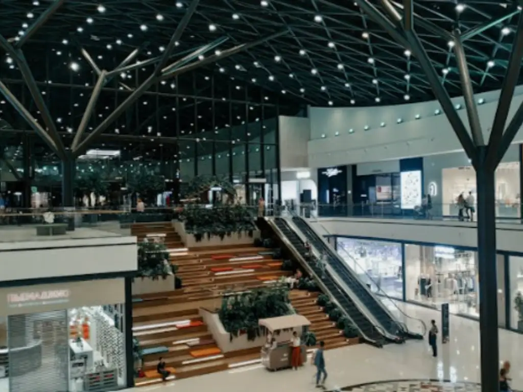
| 3.0m – 4.5m (10-15 ft) | 60° (Medium Flood) | 2.0m – 3.0m | Retail showrooms, hotel lobbies, modern supermarkets. |
| 4.5m – 8.0m (15-26 ft) | 40° (Narrow-Medium) | 3.0m – 4.5m | Light manufacturing facilities, big-box retailers, atriums. |
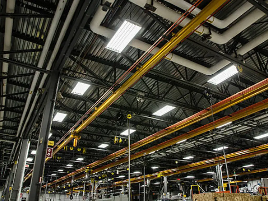
| 8.0m – 12m+ (26 ft+) | 25° (Narrow Spot) | Calculated via SC Ratio | Heavy industrial High-Bay, massive warehousing, sports arenas. |
Step 2: Selection by Lighting Objective (Aesthetic Choice)
Once Step 1 has eliminated the angles that physically will not work at your ceiling height, Step 2 defines what the light actually needs to achieve visually. Commercial lighting relies heavily on the “Contrast Ratio Rule.” In standard retail, the recommended ratio between a highlighted focal point and the general background is 3:1. You cannot achieve this if you blanket the ceiling with identical wide-angle fixtures.
| Lighting Intent | Optimal Angle Range | Visual Effect & Lux Contrast Example |
|---|---|---|
| Accent & Focus | 10° – 25° | Jewelry Display: 2000 Lux. Punches through ambient light to create deep shadows and high sparkle on specific high-margin merchandise. |
| General Ambient | 36° – 60° | Retail Aisles: 300 Lux. Provides smooth, uniform coverage that prevents eye strain while customers navigate the space. |
| Maximum Wash | 90° – 120° | Parking Garage: 150 Lux. Maximizes the footprint of the light, ensuring no sharp shadows exist behind vehicles or structural columns. |
How to Use This Protocol in the Real World:
Let’s assume you are tasked with lighting a high-end automotive showroom. You measure the ceiling height at exactly 4.5 meters (15 feet). How do you choose the right fixtures?
- Action 1 (Consult Table 1): At a 4.5m height, physics dictates your absolute maximum allowable beam angle is 60°. If you use a 120° floodlight here, the light will simply wash the upper walls and dissipate before hitting the cars. You are now safely restricted to choosing an angle between 15° and 60°.
- Action 2 (Consult Table 2): Now, what is the goal? Right above the vehicles, you want to make the metallic paint pop with high contrast. Therefore, you select a 25° Narrow Spot for those specific fixtures directly above the display. However, for the customer walkways between the cars, you need general visibility without harsh shadows. For those general areas, you select a 60° Medium Flood.
By following this two-step relationship, you have entirely eliminated the risk of a dim floor while perfectly achieving the 3:1 contrast ratio required for luxury retail.
Technical Linkage: Lumens, Candelas, and Angles
This is the deep technical water where many procurement teams and junior designers fail. A common scenario plays out across project sites daily: a contractor replaces a batch of 40° lights with new 90° lights that have the exact same wattage and Lumen output. Immediately upon installation, the client complains that the new lights look “significantly dimmer.” The contractor is confused because the spec sheet guarantees the total Lumens are identical. This is not a manufacturing defect; it is pure, unavoidable physics.
The Candela Drop: Why Wider Looks Dimmer
To understand this phenomenon, you must definitively separate total light output from directional light intensity. Lumens measure the total volume of light leaving the fixture in all directions. Candelas measure the intensity of that light in one specific direction (usually straight down to the floor).
Think of total Lumens as a fixed, one-pound piece of dough. If you squeeze that dough into a very narrow 15° beam, the center becomes incredibly thick and dense. This represents a massive peak Candela intensity, resulting in a bright, punchy spot on the floor. However, if you take that exact same one-pound piece of dough and flatten it out with a rolling pin to cover a 120° wide flood area, it covers a massive footprint, but the thickness at any given point is drastically reduced.
Governed strictly by the Inverse Square Law, as you widen the beam angle, the peak central Candelas decay exponentially. Even if a wide-angle fixture emits 20,000 lumens, its physical ability to push those lumens all the way down to a desk top is severely compromised compared to a narrow beam. It is highly recommended to consult a fixture’s 2D Candela Distribution Curve before purchasing to verify the peak intensity reaches your target working plane.
Spacing Criterion (SC) Ratio: Eliminating Dark Spots
Professional lighting design never relies on guessing how far apart to space fixtures. To calculate exact fixture quantities and mathematically eliminate dark spots, engineers use a metric called the Spacing Criterion (SC). This ratio is rigorously calculated and provided by reputable manufacturers for every specific optical lens they produce.
For a standard 40° commercial downlight, the SC ratio is typically between 0.6 and 0.8. The mathematical formula is simple: Maximum Fixture Spacing = Ceiling Height × SC Ratio.
For example, if you are installing lights in a facility with a 6-meter ceiling, and the chosen fixture has an SC of 0.7, your fixtures must be spaced no more than 4.2 meters apart (6m × 0.7 = 4.2m). If you decide to stretch them to 5.5 meters apart to save money on fixture counts, the light beams will fail to overlap at the floor level. The inevitable result is a floor that suffers from distinct “zebra striping”—alternating bands of harsh light and deep shadow that cause severe eye fatigue, decrease workplace safety, and make the commercial space look incredibly cheap.

Installation Pitfalls and Industry Blind Spots
Even if you master the math and the spacing formulas, real-world commercial environments present physical variables that can instantly destroy a perfect lighting design. You must anticipate how the architecture itself interacts with your chosen optics before issuing a purchase order.
The Dark Wall Trap: How Reflectance Eats Your Light
The Light Reflectance Value (LRV) of your interior surfaces absolutely dictates your angle strategy. LRV measures how much light a surface reflects versus how much it permanently absorbs. A standard white commercial wall has an LRV of up to 80%, meaning it acts like a giant, soft mirror, bouncing wide beams back into the center of the space and making the room feel bright and airy.
However, consider a premium restaurant, a modern hotel lounge, or a high-end residential home theater featuring dark walnut wood paneling or matte charcoal paint. These dark surfaces have an LRV of just 10% to 20%. If you install 60° wide-angle fixtures in this space, the wide light beams will hit the dark walls and be instantly absorbed. The walls will literally “eat” your Lumens. Despite having high-wattage fixtures, the room will look incredibly dim and cavernous. In any space with dark walls or dark floors, you are forced to use narrow angles (15°-24°) to bypass the absorptive walls entirely, punching the light directly down onto the white table linens or walkways where it is actually needed.
Glare, Shadows, and The Hidden TCO in High-Ceiling Environments
Specifying the wrong beam angle in a 10-meter to 15-meter industrial warehouse, manufacturing plant, or sports arena is not just a cosmetic failure; it is a highly expensive operational hazard. Using a wide 120° angle at extreme heights causes the light to hit the eyes of workers at shallow angles, creating blinding disability glare for forklift drivers navigating narrow aisles. Conversely, narrowing the angle too tightly creates deep, hazardous shadows between storage racks where light fails to penetrate.
The Brutal Reality of TCO (Total Cost of Ownership): The financial consequences of getting this wrong are severe. Failing an operational safety inspection (such as OSHA compliance) due to excessive glare or dark spots means entirely replacing the fixtures. Renting an articulated boom or scissor lift costs between $250 and $400 per day. Add in specialized union electrical labor at $85 to $120 per hour, and the facility downtime required to execute the work. Replacing just twenty incorrectly specified high-bay fixtures can instantly vaporize $5,000 to $8,000 in hidden costs, utterly dwarfing the initial unit price of the lights.
To completely eliminate these catastrophic TCO risks, WOSEN approaches high-bay industrial lighting with strict optical engineering, completely abandoning the traditional, spill-prone aluminum reflectors that plague standard fixtures. Instead, we engineer custom PC and PMMA secondary optical lenses for every high-bay unit. This physically cuts off horizontal glare, keeping the UGR strictly below 19 while maintaining a broad, even floor spread.
Precision optics alone aren’t enough; we secure your investment through an uncompromising validation process. Before deployment, our engineering team maps your facility using DIALux 3D spacing simulations to mathematically prove zero dark spots. Finally, because we are a primary manufacturer with full supply chain control, every production batch is rigorously tested in our proprietary dark room using a standard Type C Goniophotometer. This ensures the actual FWHM distribution perfectly matches the promised simulation data, entirely removing compliance risks and securing your project’s long-term profitability.
Conclusion: Final Beam Angle Checklist
Professional lighting is a science of precision, not a game of estimation. Before signing off on your next procurement order, ensure your project plan passes this three-step validation to protect your investment and ensure compliance:
- Assess the Ceiling Height Limit: Strictly use the Two-Step Matrix to cap your maximum allowable beam angle based on the physical height of the installation. Do not violate this geometric constraint.
- Define the Lighting Intent: Determine if you need an ambient wash for overall visibility, or a narrow, high-contrast punch to highlight specific tasks or premium merchandise.
- Audit Environmental Hazards: Check the Light Reflectance Value (LRV) of the walls to prevent light absorption, and calculate the exact SC ratio to ensure seamless floor coverage without glare or shadows.
Secure Your Project’s Optical Precision
Don’t risk dark spots, failed inspections, or excessive glare. Let our engineering team validate your beam angles with precise DIALux 3D simulations and proprietary PC/PMMA lens technology designed for extreme environments.
Consult an Engineer Today