On paper, many commercial LED luminaires boast perfect specifications, yet they mysteriously fail in the field months or even years before their rated lifespan. The truth is, a luminaire is not a single glowing entity, but a highly complex, interdependent system of thermal, optical, and electrical components. Understanding the intricate anatomy of these underlying parts is the only way for procurement professionals to prevent catastrophic project failures and accurately evaluate the total cost of ownership.
The Anatomy of an LED Light: Mapping the Failure Nodes
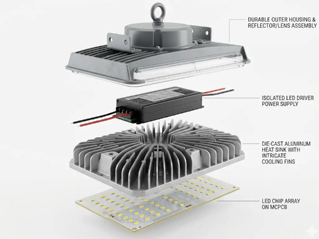
To master LED procurement, you must first visualize the luminaire from the inside out. When we mentally strip away the exterior casing, we reveal seven foundational pillars that dictate both the performance and the ultimate longevity of the product. Missing the mark on any single one of these components can trigger a domino effect of system failure.
- The LED Chip (Light Source): The microscopic semiconductor diode where the actual magic of electroluminescence occurs. It is the genesis point of both the light you want and the heat you must manage.
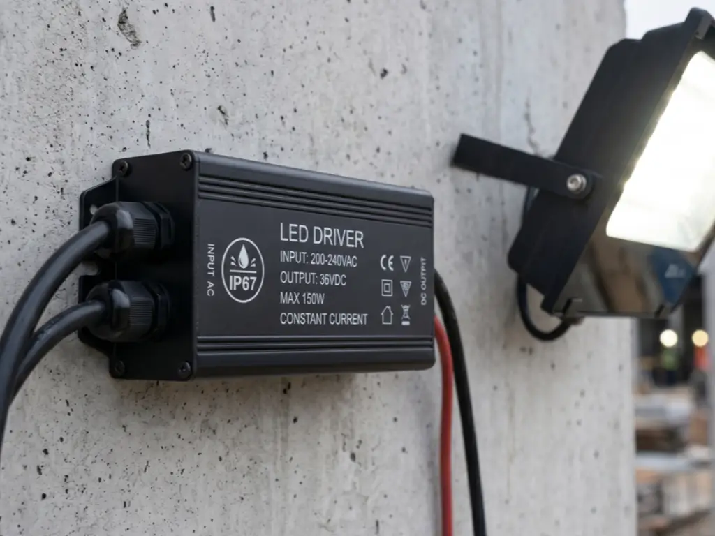
- The LED Driver (Power Supply): 💡 High-Risk Failure Node: Over 70% of premature failures occur here. This is the concealed brain of the operation, tasked with converting volatile AC grid power into smooth, constant DC current.
- The Printed Circuit Board (PCB): Serving as both the electrical nervous system connecting the chips and the crucial first bridge for thermal transfer away from the diodes.
- The Heat Sink (Thermal Management): 💡 High-Risk Failure Node: Directly impacts Lumen Maintenance. The metallic backbone responsible for drawing heat away from the PCB and dissipating it safely into the ambient air.
- Optics and Lenses: The transparent shields and engineered geometric covers that capture the raw, scattered photons from the chip and focus them into a usable, precise beam angle.
- Housing and Base: The structural armor that protects the delicate internal components from dust, moisture, and mechanical impact.
- Wires and Connectors: The internal electrical pathways and solder joints must withstand years of thermal expansion and contraction without breaking the circuit.
The Thermal-Optic System: Balancing Light Generation and Heat
The Physics of Light and Heat: Understanding the Pathway
In the realm of solid-state lighting, light and heat are inescapable twins. The fundamental physics of an LED dictate that while they are vastly more efficient than legacy incandescent bulbs, they still convert a significant portion of their electrical input into thermal energy rather than visible light. Understanding how a luminaire manages these two diverging pathways is the key to evaluating its quality.
The Light Output Pathway travels upward and outward. When electrons and holes recombine within the P-N junction of the semiconductor, photons are released. These photons must successfully travel through the encapsulating silicone, interact with the phosphor coating to achieve the desired color temperature, pass through the secondary optic or lens, and finally exit the luminaire. Any physical barrier, discoloration, or poor material choice along this upward path will absorb photons, drastically reducing the overall efficacy (lumens per watt).
Conversely, the Thermal Transfer Pathway travels downward and outward. The heat generated at the microscopic P-N junction (known as the Junction Temperature, or Tj) must be aggressively evacuated. If heat is allowed to travel upward into the phosphor layer, it will literally bake the chemicals, causing severe color shift and rapid lumen depreciation.
According to extensive reliability testing by the U.S. Department of Energy (DOE), thermal mismanagement is the primary catalyst for lumen depreciation, directly accelerating the degradation of phosphor layers and semiconductor junctions, reducing the L70 lifespan by thousands of hours.
Material Deep Dive: Substrates, Alloys, and Lenses
To keep these pathways clear, engineers must select uncompromising materials. Let us break down the physical science behind the thermal-optic components.
Light Source Packaging: SMD vs. COB Architectures
The choice of chip architecture fundamentally alters the thermal pathway. Surface-Mounted Device (SMD) technology involves spreading numerous individual diodes across a large board. This large surface area makes thermal management easier, making SMD ideal for wide-beam floodlights. However, for applications requiring intense, focused light, Chip-on-Board (COB) technology is preferred. COB directly bonds a massive array of bare LED chips directly onto the substrate. By eliminating the traditional physical lead frame found in SMD packages, COB drastically shortens the thermal path and lowers thermal resistance, allowing for an incredibly high center beam candlepower.
The Thermal Pathway: MCPCB and Aluminum Dynamics
Once heat leaves the chip, it hits the Printed Circuit Board. Standard fiberglass FR4 boards act as thermal insulators. Premium LED components demand a Metal Core Printed Circuit Board (MCPCB), typically featuring an aluminum base with a highly engineered dielectric layer, achieving thermal conductivities between 1.0 and 3.0 W/m·K.
Next, the heat reaches the Heat Sink. Cold-forged aluminum (such as AL1070) offers spectacular absolute thermal conductivity (roughly 220 W/m·K). However, die-cast aluminum (like ADC12 alloy, with a lower conductivity of around 96 W/m·K) is overwhelmingly popular in complex outdoor fixtures. The die-casting process allows structural engineers to design highly complex 3D cooling fins. This manufacturing freedom maximizes the exposed surface area for convective cooling, proving that surface area and structural geometry often trump raw material conductivity.
Optical Integrity: Phosphor and Lenses
Cheap phosphor coatings will degrade quickly under UV and thermal stress, turning a crisp 4000K white light into a sickly greenish-yellow. For the outer lenses, manufacturers must choose between Polycarbonate (PC) and Polymethyl Methacrylate (PMMA, or Acrylic). PC is virtually indestructible but prone to yellowing under prolonged UV exposure. PMMA boasts a superior light transmission rate of up to 92% and is highly resistant to UV yellowing.
The Power & Protection System: Driving Reliability
Power Architecture: Isolated vs. Non-Isolated Drivers
If the LED chips are the heart of the luminaire, the driver is the brain and the central nervous system. The driver is tasked with converting volatile AC grid power into smooth, constant DC current while simultaneously handling power factor correction (PFC) and suppressing violent electrical surges.
- Isolated Drivers: These incorporate a physical electrical separation—typically via an electromagnetic transformer—between the high-voltage AC input and the low-voltage DC output. They offer unmatched safety, vastly superior surge protection, and significantly extended lifespans, making them non-negotiable for high-end commercial applications.
- Non-Isolated Drivers: These lack a separating transformer. They are highly efficient, compact, and cheap to manufacture. However, they are highly susceptible to grid voltage fluctuations. A single violent power spike can bypass the minimal protections, instantly blowing out the entire array of LED chips.
The ticking time bomb inside most drivers is the electrolytic capacitor. Following the Arrhenius equation, the lifespan of an electrolytic capacitor is generally cut in half for every 10°C rise in ambient operating temperature. If the luminaire’s heat sink fails to dissipate heat, it slowly boils the liquid electrolyte until it dries out, causing the light to die instantly.
Chemical and Structural Defenses: Potting Compounds and Housing
In high-quality outdoor drivers, the entire circuit board is submerged in a thermal silicone Potting Compound. This thick substance hardens around the components, providing an absolute waterproof seal (IP67/IP68), dampening severe mechanical vibrations, and acting as a thermal bridge to pull heat away from vulnerable capacitors. Externally, premium luminaires utilize flame-retardant materials (like UL 94V-0 rated PBT plastics) and high-quality AWG pure copper wiring with high-temperature insulation to ensure electrical pathways survive years of thermal cycling.
Sourcing Strategy: TCO Economics and Supplier Vetting
The Hidden Cost of Cheap Components: BOM vs. TCO
When procurement managers negotiate LED sourcing, the most dangerous trap is fixating entirely on the Bill of Materials (BOM) pricing while ignoring the Total Cost of Ownership (TCO). Sacrificing material quality to save a few dollars upfront mathematically guarantees massive financial losses down the line.
Let us examine a highly realistic scenario comparing the procurement of a standard commercial luminaire versus a heavily compromised, cheap alternative over a 3-year operational period.
| Cost Metric | Premium Component Fixture | Compromised Cheap Fixture |
|---|---|---|
| Initial Unit BOM Price | $45.00 | $30.00 (Initial Savings: $15.00) |
| Internal Component Specs | Isolated Driver, Die-Cast Aluminum, MCPCB, PMMA Lens | Non-Isolated Driver, Thin Stamped Aluminum, FR4 Board, PC Lens |
| Estimated Failure Rate (3 Years) | < 1% | 30% (Due to capacitor dry-out and thermal pooling) |
| Cost of Replacement Unit | $0 (Covered by robust warranty) | $30.00 (Often voided warranties on cheap imports) |
| Labor & Truck Roll Cost per Failure | $0 | $150.00 (Electrician dispatch, high-reach equipment, downtime) |
| Total Cost of Ownership (TCO) per Fixture | $45.00 | $30.00 + (30% x $180.00) = $84.00+ |
As the data clearly illustrates, compromising on thermal-optic materials and power architecture to save $15 on the initial invoice results in a TCO explosion. True commercial sourcing demands a relentless focus on lifecycle costs over initial tags.
The Ultimate Quality Control Checklist for Suppliers
To avoid the TCO trap, procurement professionals must move past glossy brochures and interrogate the actual manufacturing capabilities of their suppliers. Before signing any bulk purchase agreement, demand clear answers to these three objective quality control questions:
- Do you operate proprietary, in-house die-casting capabilities to optimize complex thermal fin structures, or do you rely on generic off-the-shelf heat sinks?
- Are all your internal Printed Circuit Boards populated utilizing fully automated Surface Mount Technology (SMT) machinery to mathematically eliminate the risk of manual cold solder joints?
- What is your mandatory, documented pre-shipment aging test protocol, and does it subject the finished luminaires to extreme thermal stress?
How do genuine top-tier manufacturers meet these rigorous criteria? Take WOSEN LED as an objective example of this standard in action. By heavily investing in a proprietary, in-house die-casting workshop, they meticulously control the purity of raw aluminum ingots and precisely calibrate press tonnage to eliminate microscopic internal air bubbles, maximizing structural integrity and convective heat dissipation. Furthermore, they utilize fully automated Surface Mount Technology (SMT) production lines to categorically eradicate the risk of human-error cold solder joints across all critical circuit boards. Finally, before any product is authorized for shipment, it must endure a mandatory, punishing 48-hour high-temperature and high-humidity aging test. This extreme protocol acts as a ruthless filter, detonating any inherently flawed electrolytic capacitors in the factory rather than in your ceiling.
Conclusion: Making Informed LED Sourcing Decisions
The difference between a luminaire that fails in six months and one that operates flawlessly for a decade lies entirely beneath its outer shell. Arming yourself with a deep knowledge of sub-components—from the thermal conductivity of MCPCBs to the vital role of isolated drivers and rigorous aging tests—empowers you to transition from chasing the lowest BOM price to securing the most profitable Total Cost of Ownership.
Ready to Secure Your Lighting Supply Chain?
Don’t let substandard components inflate your Total Cost of Ownership. Partner with a manufacturer that controls quality from the raw aluminum ingot to the final aging test.
Consult with Our Engineering Team Today