
Ask five sources for street light pole foundation details and you will probably get five different numbers. One electrician swears by a depth rule of thumb, a parking-lot supplier quotes a range in feet, and a municipal code specifies concrete strength to the pound. The numbers conflict because each one answers a different question. This article walks the full load path instead: what the foundation actually fights, how the pole connects to it, which four inputs decide the size, and why poles still fail even when the paperwork says they should not. By the end you will know what to check on site and what to demand from suppliers before the concrete truck arrives.
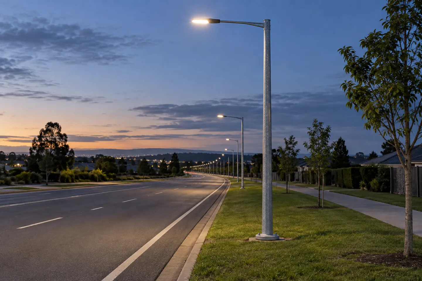
What a Street Light Pole Foundation Actually Does
A street light foundation is a reinforced concrete block buried in the ground, and its whole job is to keep a tall lever from tipping over. Every force on the pole above (wind pushing on the pole, the arm, and the luminaire) turns into an overturning moment at ground level. The foundation resists that moment with its own weight, its shape, and the soil gripping it.
Notice what is missing from that sentence: the lamp’s own weight barely figures. Poles rarely fall straight down. They rotate out of the ground, so wind exposure drives the design far more than dead load does. A squat, heavy base on weak soil can lose to a smaller base sitting in firm, well-compacted ground.
Cars bump poles. Snow plows pile against them. These are secondary loads, but they explain why undersized bases let poles drift out of plumb over the years even in calm districts.
One piece of folk wisdom to discard early: the “bury ten percent of the height plus two feet” rule you may have seen applies to wooden utility poles, a different structure class with different failure criteria. Street lighting poles are engineered against overturning, and their foundations follow lighting practice, not fence-post habits.
That phrase “gripping it” in the first paragraph is where most trouble starts. The concrete is rarely the weak link; the soil around it is. And between the pole and the concrete sits a connection whose details decide whether the whole chain holds, which is where we go next.
Three Ways a Pole Meets Its Foundation
The most common arrangement on commercial and municipal work is the anchor-bolt flange base. Four steel anchor rods are cast into the concrete with their threads left projecting above the top. The pole arrives with a base plate that slips over the rods, sits on leveling nuts, gets checked for plumb, and is then sealed with a grout layer under the plate. The template that holds the bolts in position during the pour matters more than it looks: if the bolt circle comes out distorted, the pole cannot be mounted without cutting or re-bending rods.
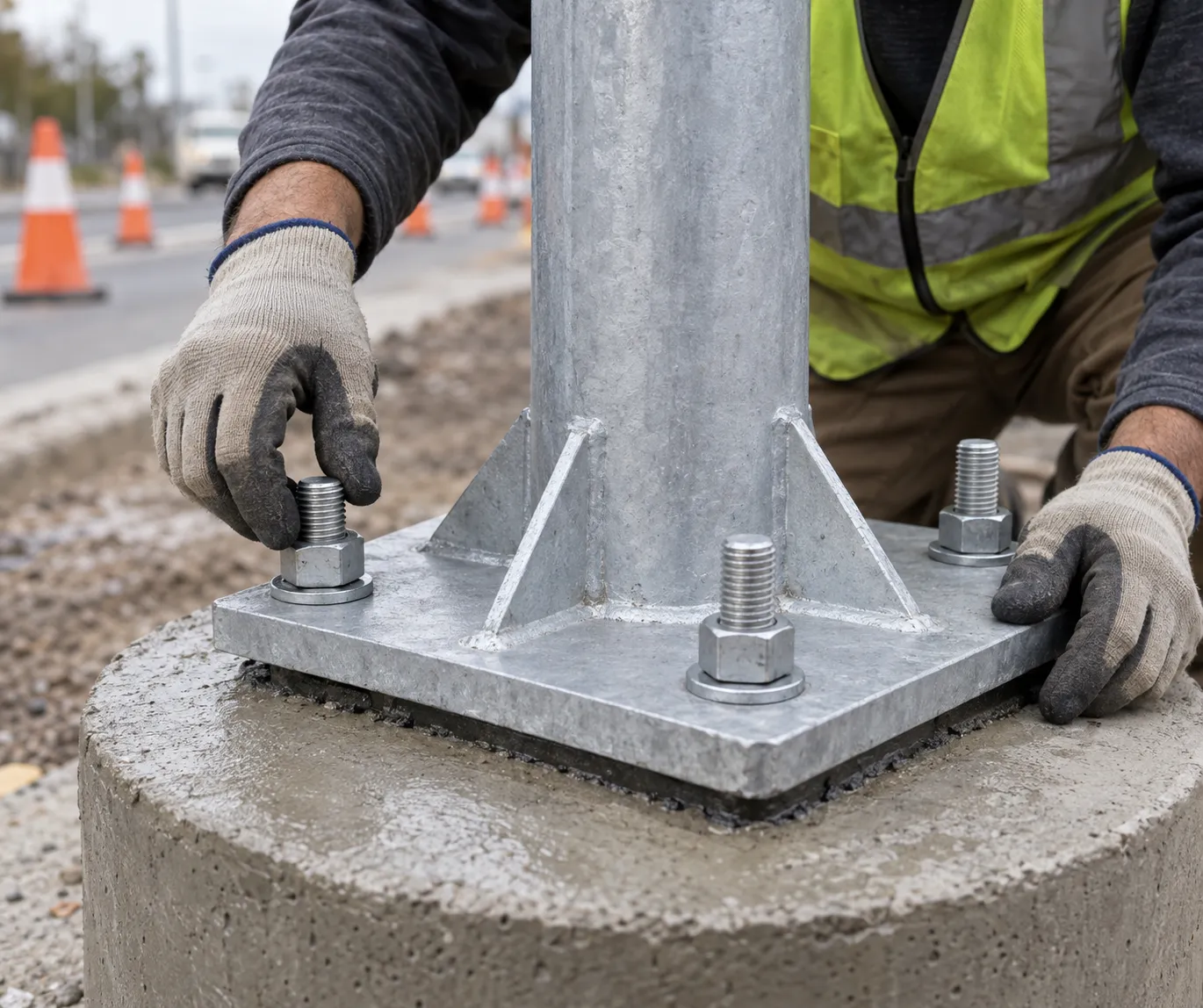
Direct burial is the second approach: the pole shaft itself extends into the excavation and concrete (or compacted soil) grips it directly. Fewer parts and faster on rural or low-height work, but the below-grade section lives permanently in a corrosion-prone environment, and the pole cannot be swapped without digging it out.
A third option, the helical screw pile, rotates into the soil like a giant screw and receives the pole on a flange. You will meet it mostly on temporary works, soft soils, or fast schedules where excavation is impractical. It is a niche solution rather than a competitor to the two main methods.
| Connection | Installation notes | Best fit | Watch out for |
|---|---|---|---|
| Anchor-bolt flange (most common) | Cast bolts with a positioning template; set pole on leveling nuts, check plumb, then grout under base plate | Municipal roads, parking lots, any engineered work | Bolt-circle distortion in the pour; thread protection; corrosion under the plate |
| Direct burial | Drop and backfill or concrete the shaft in one operation | Rural roads, low poles, quick jobs | Below-grade corrosion; frost depth; pole is not recoverable |
| Helical screw pile | Screwed into soil by machine, pole bolted to flange | Temporary lighting, soft ground | Lower moment capacity; needs torque-calibrated installation |
Whichever method you choose, corrosion starts at the interface. The splash zone around grade, the gap under the base plate, and any backfill left uncompacted against the shaft are the places water sits and rust works. State standard details reflect this. One Illinois District drawing calls for anchor rods projecting 2¾ inches above the foundation, with raceways stubbed an inch higher (Illinois DOT, n.d.). New Hampshire’s standard plan specifies four ¾-inch bolts equally spaced on a 12¾-inch bolt circle (NH DOT, 2010). In the same spirit, regional street-light notes size bolts by pole gage: 1 inch by 36 inches for lighter poles and 1⅛ by 40 inches for heavier sections (RTC Southern Nevada, 2024).
Before you commit to either main method, two checkable actions. Confirm the bolt positions with a template before the pour, and verify the bolt-circle diagonals after it. If you are considering direct burial, check the local frost line and water table first: both change the burial depth and the corrosion exposure.
What Really Decides Foundation Size (and Why the Rules Conflict)
Here are three rules you can find in the wild: bury one foot for every five feet of pole. Use three to six feet and be done. Make the concrete diameter three times the bolt circle. A practitioner on the Mike Holt engineering forum explains his own version (Mike Holt Forums, 2006). A 20-foot pole usually carries an 8-inch bolt pattern, so he pours a 24-inch diameter pier and goes 4 feet deep, undercutting the bottom for grip. A commercial supplier’s guide puts typical parking-lot depths at 3 to 6 feet, deeper in wind or poor soil (LED Light Expert, 2024). All of these “work,” and that is exactly why they contradict each other. Each one is a local approximation of four inputs that the rule-of-thumb author had frozen at typical values.
The Four Inputs Behind Every Foundation Number
Pole height and arm
Height sets the lever; the outreach arm lengthens it again.
Design wind speed
Moment scales with the square of speed, so coastal and inland sites never share a table.
Soil
Bearing capacity, fill, water table and frost line decide what the ground can resist.
Fixture EPA and weight
The input the guides forget: the luminaire’s wind-catching area and mass.
The first input is the pole itself: height, and just as important, the arm. A 30-foot pole with a 6-foot outreach arm applies a much longer lever than the same pole with a short arm.
The second input is wind. Codes assign design wind speeds by region, and the moment at the base scales with the square of that speed. Coastal hurricane territory and sheltered inland valleys do not share a foundation table, even for the identical pole.
The third input is soil. Bearing capacity, whether the ground is undisturbed or recent fill, the water table, and the frost line all change how much the ground can resist. One municipal code writes its concrete requirements around this reality, requiring air-entrained concrete with a 3-inch maximum slump and a minimum 14-day strength of 3,500 psi from an approved mix (East Dundee Code §57.144, n.d.).
The fourth input is the one almost never mentioned in the guides: the fixture side. That is where we are headed in a moment, because it quietly breaks every generic table.
Typical Ranges by Pole Height (and What They’re Worth)
| Pole height | Commonly published practice | Source system | What it is worth |
|---|---|---|---|
| 15–20 ft (4.5–6 m) | 24-inch round pier, ~4 ft deep; or 600×600 mm square, ~1.2 m deep; 3–6 ft commercial range | Electrician rule of thumb; South Asian construction practice; US parking-lot guides | A sanity check, not a design. Assumes modest arm, moderate wind, decent soil |
| 25–33 ft (8–10 m) | Same section family, deeper and wider; bolt circles in the 11–13 inch range on US drawings | State DOT standard details | Must be confirmed against the actual wind zone and soil report |
| 39 ft (12 m) and above | Engineered per project; depth reduction rules apply only with better soils | DOT details and project specs | No public table is defensible; require a calculation |
Treat the first row as a plausibility filter. If your project sits in a coastal wind zone, on fill, or under a large luminaire, the ranges are void and a calculated design takes over. Official details make the same point by omission: the Illinois foundation drawing ties depth and bolt circle to the specific mounting height and pole type rather than publishing one universal number (Illinois DOT, n.d.).
Concrete deserves one more line here. The spec that matters is the one in your project documents, and a typical US municipal anchor is that 3,500-psi, air-entrained, 14-day figure cited above (East Dundee Code §57.144, n.d.). Standard practice treats 28 days as full design strength, so whether you can stand the pole at 14 days is a specification question, not a habit question.
Where the Fixture Side Enters the Math
EPA stands for effective projected area: the frontal area of the luminaire and arm that the wind pushes, in square feet. It belongs in the moment calculation just as much as pole height does. Swap a slim 60-watt road optic for a large area-light body on the same pole and the wind load at the top grows, which grows the overturning moment, which grows the foundation. The pole drawings assume some EPA limit; the foundation assumes the loads that come with it.
Solar all-in-one street lights push this further. The photovoltaic panel is a sail, the battery and luminaire sit high on the mast, and the whole assembly is top-heavy by design. On a Lagos rural road project, 250 sets of 100 W all-in-one units were installed in 2019 with foundations sized for exactly this kind of assembly (WOSEN project report, 2019). A foundation copied from a grid-powered neighbor’s work may be the wrong foundation for a solar mast of the same height.
The procurement consequence is simple to state and easy to skip. Get the luminaire’s EPA and weight, the anchor-bolt template, and the supplier’s foundation recommendation before the civil design is finalized. Without those numbers the base is designed on assumptions, and the three “voiding conditions” are any change of wind zone, untreated fill, or a fixture swap after the pour.
Pouring It Right: The Installation Sequence
Start before the excavation. Confirm the position against the lighting plan, clear the utilities, and look at the soil the design assumed. If the crew meets fill, water, or a soil that plainly does not match the drawing, stop and send it back for review rather than improvising a bigger hole.
Excavate to the specified depth and width, then set the steel. Standard details tell you what the cage should look like. The Illinois drawing, for example, calls for a #3 spiral at a 6-inch pitch or ties at 12 inches on center (Illinois DOT, n.d.). Fix the anchor bolts to the positioning template, stub the conduits above the future top of concrete, and check every measurement before the truck arrives.
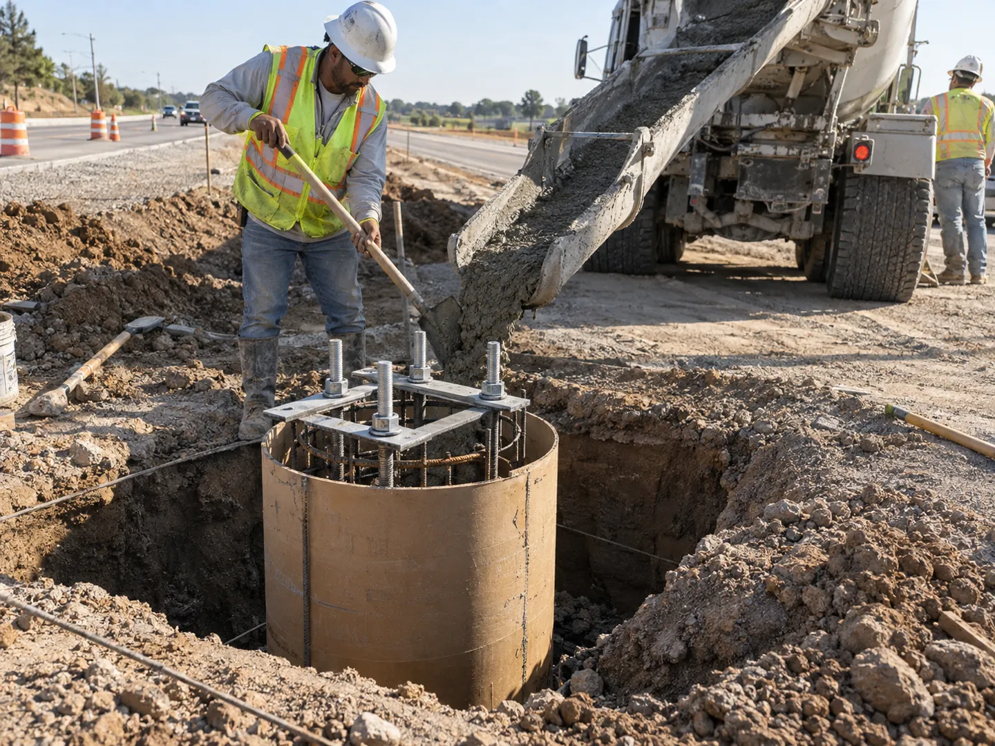
Pour in one continuous operation, vibrate properly, and finish the top level. Then comes the step crews are tempted to skip: curing. The design documents govern when the pole may be erected; if your specification uses a 14-day minimum strength, erecting on day 7 is not an optimization, it is a deviation.
Erection day has its own order. Set the pole over the bolts onto the leveling nuts and pull it plumb; the DC DOT standard says it plainly: set plumb using leveling nuts on the anchor bolts (DC DOT, n.d.). Torque the top nuts to the specified values, grout under the base plate, and backfill in compacted lifts. Finish with a slight slope so water drains away rather than pooling at the shaft.
The Installation Sequence at a Glance
- 1
Survey and clearances. Confirm the soil matches the design; a mismatch means stop and return to design.
- 2
Excavate and set steel. Cage per the detail; anchor bolts fixed to the template; conduits stubbed high.
- 3
Pour and cure. One continuous pour; erection only at the specified strength (14-day minimum in the cited municipal spec).
- 4
Erect and finish. Plumb on leveling nuts, torque to spec, grout, backfill in compacted lifts, slope for drainage.
- 5
Record. Photos at each stage, torque log, cure dates.
Leave evidence at every step: photos of the template and rebar before the pour, the concrete delivery tickets, the torque readings, the cure dates. The next section explains why those records are not bureaucracy but the difference between a defensible installation and an argument.
Why Poles Still Fail: Failure Modes and Site Checks
Compliant on Paper, Failed in the Field
When Hurricane Ian crossed Florida in 2022, aluminum light poles on a Central Florida bridge collapsed and cracked even though wind speeds stayed below the structures’ design limits. University of Florida researchers found that hidden air pockets inside the pole metal weakened the bases by as much as 25% (University of Florida ESSIE, 2026). Small installation issues added enough stress to push the assemblies past what remained.

Hidden air pockets cut some pole-base capacity by as much as 25%, and the poles still fell with the storm below their design wind speed.
That sentence is worth rereading, because it breaks the comfortable assumption that a stamped drawing plus a passing inspection guarantees anything. Codes set minimums on paper. What happens between disciplines (casting quality, bolt torque, backfill compaction, the fixture actually delivered versus the fixture assumed) decides whether the minimum is met in the ground. The researchers’ own conclusion was that quality control and installation practice need as much attention as the design numbers.
Five Failure Modes and the Checks That Catch Them
| Failure mode | Field cause | Checkable action |
|---|---|---|
| Overturning | Design wind zone exceeded, or backfill never compacted | Compare site wind zone against the design basis; demand compaction records per lift |
| Root corrosion | Ponding water, damaged coating at grade, no concrete collar or slope | Inspect the grade line and splash zone; verify drainage slope away from the shaft |
| Scour and undermining | Flood flow or poor drainage washing soil from around the base | Inspect foundation exposure after heavy rains and flood season; restore and protect eroded ground |
| Internal voids and casting defects | Poor casting quality or unchecked material | Request material and casting QC records from the supplier; simple sounding inspection on suspect units |
| Progressive tilt | Early erection before specified strength, uneven bolt torque | Keep cure-date records; torque in the specified sequence and log the readings |
Field finding — Hurricane Ian, 2022
−25%
Meeting the design code did not save these poles.
Hidden voids weakened the pole bases by up to 25%, and the storm stayed below design wind speed — quality control across the whole chain is part of the structure.
Every row in that matrix produces a document: a compaction record, a torque log, a cure date, a supplier QC file. When a pole leans years later, those papers decide whether the fix is a warranty claim or a court case. The party best placed to close the loop on several rows is the fixture and pole supplier, which is where the checklist below comes from.
What to Demand Before You Pour
Reread the size section and notice where half of the inputs live: on the fixture side. The EPA figure, the weight, and the bolt template belong to a luminaire that may still be undecided when the foundation is poured. That observation converts directly into procurement language. Structural data completeness belongs on the evaluation sheet at the same rank as lumen output and unit price, because a missing EPA figure is a hidden change order on the civil side.
The failure section converts just as directly. The researched failure concentrated in interfaces and quality transparency. So the handover meeting should have the pole and luminaire supplier in the room. The acceptance records should cover anchor torque and the grout layer, not just the concrete pour. A supplier that delivers this data willingly is telling you something about how the rest of the project will run.
Before the Pour
Luminaire EPA and weight received and entered in the foundation design.
Anchor-bolt template drawing matched to the pole base plate.
Wind zone and soil assumptions confirmed against the site report.
Supplier’s foundation recommendation on file (solar assemblies especially).
Evidence plan agreed: photos, torque log, cure dates, compaction records.
That is the standard we work to at WOSEN, an LED street light manufacturer. We answered a Lagos township’s road-safety problem with 250 sets of 100 W all-in-one solar street lights in 2019 (project reference). We supply the structural data package (EPA, weight, bolt template, foundation recommendation) with our street light lines such as the 220 lm/W, IP66-rated LUMINA series. And we answer technical requests within 12 hours. Bring us your pole schedule and soil report before the civil design freezes, and the foundation will be sized for the light that actually arrives on site.
Send Us Your Pole Schedule and Soil Report
WOSEN engineers return the structural data package and a foundation-ready lighting proposal within 12 hours — for grid-powered and solar street light lines alike.
Get a Foundation-Ready QuoteReferences
- University of Florida ESSIE. “Why light poles failed in Hurricane Ian despite meeting design standards.” 2026. https://essie.ufl.edu/why-light-poles-failed-in-hurricane-ian-despite-meeting-design-standards
- City of East Dundee, IL. “Code of Ordinances §57.144 Light Pole Foundations.” n.d. https://codelibrary.amlegal.com/codes/eastdundee/latest/eastdundee_il/0-0-0-30915
- Illinois Department of Transportation, District 1. “BE300 Light Pole Foundation Detail.” n.d. https://apps1.dot.illinois.gov/eplan/desenv/standards/District%201/D1DistrictStandards/PDFs/Individual_22x34/be300_22x34.pdf
- New Hampshire Department of Transportation. “Standard Plan SL2, Street Light.” 2010. https://www.dot.nh.gov/sites/g/files/ehbemt811/files/inline-documents/2010_sl_2.pdf
- RTC Southern Nevada. “Streetlight Standard General Notes.” 2024. https://www.rtcsnv.com/about/wp-content/uploads/sites/3/2024/11/Item-3-Handout.pdf
- DC Department of Transportation. “Section 600: Typical Details of Light Pole Installation.” n.d. https://ddot.dc.gov/sites/default/files/dc/sites/ddot/publication/attachments/Section%20600%20%28614%20Part%202%20-%20614.13%20-%20614.24%29.pdf
- Mike Holt Forums. “Light pole bases.” 2006. https://forums.mikeholt.com/threads/light-pole-bases.29873
- LED Light Expert. “Parking Lot Light Pole Bases Guide.” 2024. https://www.ledlightexpert.com/parking-lot-lights-bases-guide
- WOSEN. “Road Light Project in Rural Township, Lagos, Nigeria.” 2019. https://www.wosenled.com/projects/road-light-project-in-rural-township-lagos-nigeria/
- WOSEN. “Series LUMINA Adjustable LED Street Lights.” n.d. https://www.wosenled.com/portfolio/series-lumina-adjustable-led-street-lights/
- WOSEN. “LED Street Lights (product category).” n.d. https://www.wosenled.com/outdoor-lights/led-street-lights/
- WOSEN. Homepage. n.d. https://www.wosenled.com/

 English
  Spanish
  French
  German
  Italian
  Arabic
  Russian
  Portuguese
  Dutch
Dutch  Indonesian
  Turkish
  Polish