
A warehouse crew finishes a retrofit on Friday. Forty new high bay fixtures hang at 9 meters, wired to three switches, everything lit and signed off. On Monday the facilities manager asks for one more feature. The rows near the loading dock should run at half output during idle hours. The crew opens a fixture and finds two extra wires, purple and gray. The dimming question was never a switch question. It was decided at the factory, and possibly at the purchase order.

First Check: Is the Fixture Dimmable at All
Every LED high bay has a driver, and the driver decides everything about dimming. If the driver is a non-dimmable type, no wall control, sensor, or smart module will change that. This is why the first move is not buying a dimmer. It is confirming what is already hanging above your floor.
Three checks settle it. First, read the spec sheet for an explicit dimming entry, ideally naming a method such as 0-10V rather than a bare “dimmable” claim. Second, open the driver compartment and read the label on the driver itself, which should state the control interface it accepts. Third, look for the control pair entering the wiring compartment: on most North American fixtures these are a purple wire (Dim+) and a gray or pink wire (Dim-).
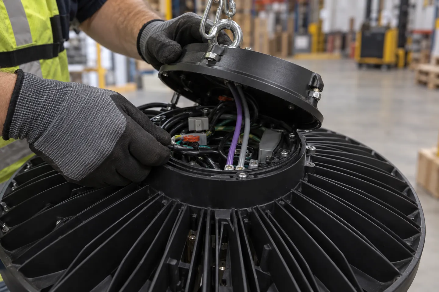
One clarification keeps the rest of this article clean: dimming here means electrical dimming, where the driver reduces LED current on command. Covering a lens with film or tape is light control of a sort, but it wastes the fixture’s efficiency and turns heat inward. Nothing in the sections below involves that approach.
What if the purple and gray wires just stay unconnected? Nothing bad. The driver runs at full output, and the fixture behaves like a plain on-off light. The failure mode runs the other way. Boards marked “nondim” occasionally ship inside fixtures sold as dimmable, and they flicker or fail early once someone wires them to a dimming circuit. Spec sheets describe the design, not always the batch. Matching the driver label against the batch you actually received is the thirty-second check that prevents a season of callbacks.
The three-point dimmability check
- Spec sheet names a dimming method, not just “dimmable”
- Driver label states the accepted control interface
- Purple Dim+ and gray Dim- control pair present in the wiring compartment
If all three pass, the fixture is dimmable by design. Verify the board marking matches the batch before bulk wiring.
The 0-10V Standard and What the Alternatives Actually Buy
The method list on most product pages reads the same: 0-10V, sensors, wireless, maybe DALI. What the list does not explain is that these are not four ways to do one thing. They sit at different layers, and each one buys something specific. Knowing what each buys is what keeps a budget honest.
0-10V, the default for a reason
In a 0-10V system the driver generates a small DC control voltage, and the controller pulls that voltage down to set the level. Ten volts means full output, lower voltage means lower output, and depending on the driver, 0V means minimum or full shutdown. The control pair carries signals, not load current, which is why thin 16-18 AWG wire handles it. The interface itself is defined by ANSI C137.1 and IEC 60929 Annex E (ETC, 2017).
Two traits explain why this became the high bay default. It is cheap: the dimming electronics live inside the driver that is already there, so the fixture premium is small. And it is legible: an electrician who has wired one 0-10V high bay can wire four hundred, because the topology never changes.
No universal dimmer
A 0-10V driver needs a 0-10V wall controller. A phase-cut model chops the AC waveform instead, and a 0-10V driver ignores that chop entirely: the pair runs full-brightness only, or flickers and buzzes. Match the wall device to the driver interface, and state the method on the submittal.
Drivers also differ in what happens at the bottom of the range. A dim-to-min driver holds a pilot output, often around 10%, and never goes dark; a dim-to-off driver extinguishes at 0V. Neither is wrong, but a storage aisle planned for near-dark standby needs the second type, and that distinction lives in the driver datasheet, not on the box.
1-10V: the lookalike that is not interchangeable
The 1-10V interface looks identical on a wiring diagram but works in the opposite direction. The driver sources the control current and the wall device attenuates it, so the fixture can dim very low yet cannot switch itself off. The mains side still needs a relay or switch (Acuity Brands, 2024). It survives mainly in European-spec equipment. Connecting a 1-10V controller to a 0-10V driver, or the reverse, can feed current the wrong way through an input that was never designed for it. When a project mixes regions, the control method belongs on the submittal, not in an assumption.
DALI: paying for addressing and feedback
DALI replaces one analog signal with a digital bus. Each driver gets an address, and groups and scenes become software settings. The driver also reports status back, so a failed unit announces itself instead of waiting for a work order. That capability costs real money: bus power supplies, commissioning time, and controls expertise on staff. For a single-open-plan warehouse with three rows of high bays, DALI buys nothing that a 0-10V zone cannot. For a multi-tenant facility with hundreds of fixtures under scheduled management, the addressing pays for itself in reduced service runs.
Wireless: when the wire run costs more than the module
Wireless control kits place a receiver module at the fixture group and let battery switches or sensors talk to it, which moves the expensive part. The control wiring shrinks to short jumpers between module and drivers, and the wall locations become adhesive-mounted remotes. It earns its cost in finished ceilings, block walls, and multi-switch retrofits. The trap is capacity: these modules have finite load and driver-count limits, and discovering the limit after purchase turns a weekend job into a re-order (more on sizing below).
High bay dimming options compared
| Method | Signal | Lowest output | Added cost tier | Best fit |
|---|---|---|---|---|
| 0-10V | Analog DC, 2-wire | 0-10% depending on driver (dim-to-off vs dim-to-min) | Low (driver-integrated) | Warehouses, gyms, workshops, most retrofits with access |
| 1-10V | Analog DC, reversed current flow | Near 0% but no self-off | Low, European-spec equipment | EU-specified fixtures only, never mixed with 0-10V |
| DALI | Digital bus, addressed | 0-1% typical | Medium-high (bus PSU + commissioning) | Large managed buildings needing feedback and scenes |
| Wireless kit | Radio (Zigbee, Bluetooth, proprietary) | Depends on paired driver | Medium (modules + remotes) | Finished ceilings, block walls, multi-switch retrofits |
| Phase-cut wall dimmer | AC waveform chop | Not applicable | n/a | Not compatible with 0-10V high bay drivers |
Plan It In or Bolt It On Later
Dimming costs least when it is decided before the fixtures go up. In new construction, the control pair rides along in the same wire pulls as the power, and the incremental labor is close to zero. The decision that remains is specifying the right driver and reserving wall space for a 0-10V controller instead of a plain switch.
Installed bases get the harder conversation, which really has three versions. If the purple and gray control pair already runs fixture to fixture, adding dimming is a wall-device swap, an hour of work per zone. If the control pair was never pulled, two options remain. One is running Class 2 control wire as a surface or exposed run. The other is jumping to a wireless kit and letting radio replace the copper. If the drivers themselves are non-dimmable, no retrofit path exists short of fixture replacement, and that fact is invisible from the floor.
Send WOSEN your fixture count and ceiling constraints, and we will tell you which retrofit path your drivers qualify for.
Get a Retrofit AssessmentThat last case is why retrofit feasibility deserves a verdict before a budget. The check order is: driver type first, then wire paths, then controls. Reversing the order produces quotes for systems that cannot physically exist.
The pressure to retrofit keeps growing for a reason that has nothing to do with comfort. A 2011 meta-analysis of field studies put typical occupancy-sensor lighting savings at 25-40%, varying widely by space type (Williams et al., 2011). Current editions of ASHRAE 90.1 go further and require general lighting to reduce or shut off when spaces are unoccupied (inside.lighting, 2026). Codes keep pulling controls from option to requirement, which means more buildings will face this retrofit decision with fixtures already in the air.
New install vs retrofit paths
| Path | Precondition | Cost tier | Verdict |
|---|---|---|---|
| Plan at install | Control pair pulled with power | Near zero marginal | Always preferred |
| Retrofit A: wires present | Purple/gray pair in place | Wall device + an hour per zone | Cheap, do it |
| Retrofit B: no wires | Access for Class 2 run OR wireless viable | Medium (labor or modules) | Pick wireless when ceilings or walls are closed |
| Retrofit C: non-dimmable drivers | None that helps | Fixture replacement | No retrofit exists, re-spec the fixture |
Wiring and Sizing: How Many Lights per Dimmer
The estimating question that decides whether a dimming job is profitable: one controller, how many fixtures? Get this number wrong in either direction and the symptoms look identical at commissioning, so it pays to do the arithmetic before the wire cart leaves the shop.
Do the dimmer math before the wire run
A 0-10V controller does not carry the fixtures’ power. It only manages the control pair, and each connected driver draws a small control current from that pair. The controller must be able to absorb all of it, which manufacturers call sink capability. The sizing rule is one division: maximum drivers equals the controller’s sink capability divided by the per-driver source current (Lutron, 2014).
The commonly referenced ceiling for a single driver is 2 mA. A typical wall controller sinks around 50 mA, which yields 25 drivers per controller at that full draw. Panel-style controls sink more; one manufacturer documents 100 mA of sink capacity, enough for 50 drivers at 2 mA each (ETC, 2017). Field numbers run friendlier. Many drivers draw 0.5 mA or less on the control pair, which is why commercial crews sometimes commission far more than 25 fixtures per zone without symptoms (Mike Holt Forum, 2024). The honest planning number comes from the driver datasheet. When the datasheet is silent, take it from a meter. Set a multimeter to DC milliamps, connect it across the fixture’s control pair with the fixture powered and no controller attached, and read the actual draw.
Worked example: 14 high bays, one zone
Required sink: 14 x 2 mA = 28 mA
Datasheet control draw: 2 mA per driver. A standard 50 mA wall controller carries it with margin.
If the datasheet lists 5 mA per driver instead, required sink becomes 70 mA, and the standard wall controller is undersized before a single wire is pulled.
Cable: Class 2 freedom, Class 1 rules
The 0-10V pair is low-voltage Class 2 wiring, which buys real freedom: it can run exposed along framing in most jurisdictions, stapled where a raceway would be wasted effort. The freedom ends at the raceway. When control conductors share a conduit, junction box, or cable sheath with power conductors, every conductor in that raceway needs insulation rated for the highest voltage present, typically 600V. Bell wire inside a power conduit is a violation even if the electrician is careful. Manufacturers solve this by offering MC luminaire cable with the purple and gray control conductors built into the same 600V-rated jacket as the power conductors, one pull, all compliant. For long runs or electrically noisy buildings, a shielded 16/2 or 18/2 control cable keeps the analog signal stable. Every joint should land with consistent polarity: purple to Dim+, gray to Dim-. A reversed pair reads as a fault, not a dim level.
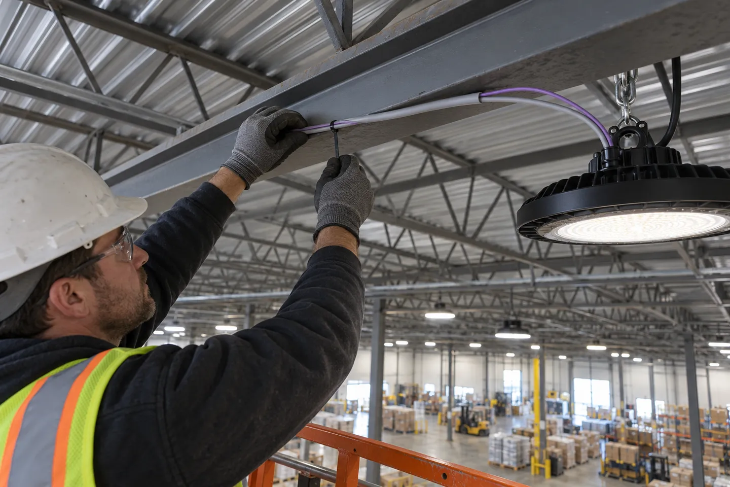
Topology: one zone or three
Zones multiply control pairs, not power circuits. Eight fixtures on one dimmer need one control run; the same eight split into two zones need two, each landing on its own controller. This is where wireless kits justify themselves: the module consolidates the control pair terminations at the fixture group, and wall locations become battery devices. The same sizing math applies to the module, with one extra check that has burned more than one installer. Wireless relay modules carry their own load limits in amps on the power side. A module chosen for its radio features can still be undersized for eight amps of drivers on one circuit.
Large halls add a classic pattern: contactors. Where rows switch through contactors, the dimmer never sees fixture load at all, only the contactor coils. An 8 A-rated low-voltage dimmer therefore happily commands a gym’s worth of light. The control topology and the power topology are separate drawings, and confusing them produces both undersized dimmers and laughably oversized ones.
Sensors close the loop
An occupancy sensor or photocell plugs into the same control pair, typically by taking over the sink role. No motion, and the sensor pulls the signal down. Daylight flooding in, and the sensor eases output back. Standby depths of 50-60% are common for aisles and storage zones, with full output on detection. At that point dimming stops being a comfort feature. It becomes the mechanism behind the 25-40% savings figures from the field studies, because the fixtures spend their lives at partial output instead of full.

When Dimming Goes Wrong: Diagnosis and Boundaries
Dimming failures cluster into a handful of patterns, and each one points at a different responsible party. Working symptom-first keeps the blame accurate, which matters when the invoice goes out.
Dimming fault diagnosis matrix
| Symptom | Likely root cause | Responsibility | Verifiable action |
|---|---|---|---|
| Fixture ignores dimmer entirely | Non-dimmable driver installed, or control pair never terminated | Product supplier or installer | Open driver compartment, check board marking and dimmer terminals |
| Flicker only at low settings | Driver minimum below controller range, or dimmer-driver incompatibility | Spec or controls selection | Test with a known-good 0-10V controller, note the level where flicker starts |
| Audible buzz from fixtures | Phase-cut dimmer on a 0-10V driver, or loose core in fixture | Installer | Swap the wall device for a 0-10V type, one test fixture first |
| End-of-run lights dim incorrectly | Control pair capacity exceeded (sink current), or polarity reversed at last junction | Installer or estimator | Re-run the sink math, measure per-driver draw, check polarity labels |
| Whole batch ages out early | Drivers ran for years on a dimming circuit they were not built for, heat stress | Product supplier or spec | Check board markings against order, batch numbers, and warranty terms |
The matrix row that deserves a full telling: a facilities team reported 15 of 40 high bay fixtures failing within a couple of months, about six years after installation. The fixtures had never dimmed cleanly; they flickered whenever anyone tried, so the staff kept them at 100% and figured that settled it. When the failed units came down, the driver boards were printed “nondim”. Non-dimmable fixtures had been installed on a dimming circuit, ran misapplied for years, and aged out early. They died past the warranty window, with paperwork describing a product that was not in the ceiling. That sentence is worth repeating to anyone who writes purchase orders: the board said nondim, and the spec sheet said dimmable, and the fixtures paid the difference.
Heat closes the loop on why misapplied drivers fail rather than just misbehave. In UFO-style high bays the driver sits close to the LED board, so a driver already running outside its comfort zone ages inside an oven. The failure shows up years later as a dead fixture, and by then the chain of custody has gone cold.
The nondim callback
15 / 40
high bays dead within two months, six years after install
driver boards stamped nondim, sold as dimmable
Writing Dimming Into the Spec
Every failure above was a specification failure wearing a work uniform. The nondim boards, the undersized controllers, the mixed 1-10V equipment: all of them were settled by paperwork before anyone touched a ladder, just settled wrong. The fix costs minutes on a request for quotation.
Seven lines do most of the work. Name the protocol explicitly: “0-10V dimming per ANSI C137.1,” never the word “dimmable” alone.
The seven-line dimming spec
- Protocol written as a standard, not an adjective: 0-10V dimming per ANSI C137.1
- Minimum dimming depth stated, plus dim-to-off or dim-to-min behavior
- Per-driver control draw capped at 2 mA, figure required on the datasheet
- Flicker referenced against IEEE 1789
- Driver tier matched to the fixture warranty class
- Certifications named for the destination market: UL and DLC for North America, CE and RoHS for Europe
- Acceptance test on the sample: dim to minimum under load, then measure the per-driver draw
None of that is exotic. Every line is a field failure from the sections above, translated into a sentence a supplier can price against. The rework that follows a missed spec line is measured in crane rentals and dark shifts; the spec line costs nothing but the writing.
One boundary belongs in the contract, not just the spec. Damage from misapplication generally falls outside warranty coverage, whether it is non-dimmable drivers on dimming circuits, reversed control pairs, or undersized controllers. The product was used outside its stated conditions. The acceptance test in the sample stage is what keeps that boundary from becoming a dispute.
WOSEN’s LED high bay lights carry UL, ETL and DLC listings for North America plus CE and RoHS certifications, with a five-year warranty as standard.
Spec Your High Bay Dimming With WOSEN
UL, ETL and DLC listings for North America, CE and RoHS for Europe, five-year warranty as standard. Send your fixture list for a driver-level quote.
Request a QuoteReferences
- ETC. “Understanding 0–10 V LED Drivers.” White Paper, Revision D, 2017.https://www.etcconnect.com/workarea/DownloadAsset.aspx?id=10737502527
- Lutron. “0–10 V Control Topology.” Application Note No. 587, 2014.https://assets.lutron.com/a/documents/048587_web.pdf
- IEEE. “IEEE 1789-2015: Recommended Practices for Modulating Current in High-Brightness LEDs for Mitigating Health Risks to Viewers.” 2015.https://standards.ieee.org/standard/1789-2015.html
- Williams, A., et al. “A Meta-Analysis of Energy Savings from Lighting Controls in Commercial Buildings.” LBNL-5095E, 2011.https://eta-publications.lbl.gov/sites/default/files/a_meta-analysis_of_energy_savings_from_lighting_controls_in_commercial_buildings_lbnl-5095e.pdf
- inside.lighting. “Lighting Controls Take Focus in the Latest 90.1 Energy Standard.” 2026.https://inside.lighting/news/26-06/lighting-controls-take-focus-latest-901-energy-standard




 English
 Spanish
 French
 German
 Italian
 Arabic
 Russian
 Portuguese
 Dutch
 Indonesian
 Turkish
 Polish