
What Actually Turns a Street Light On
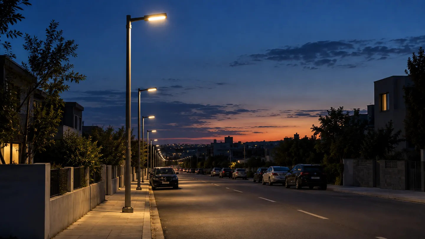
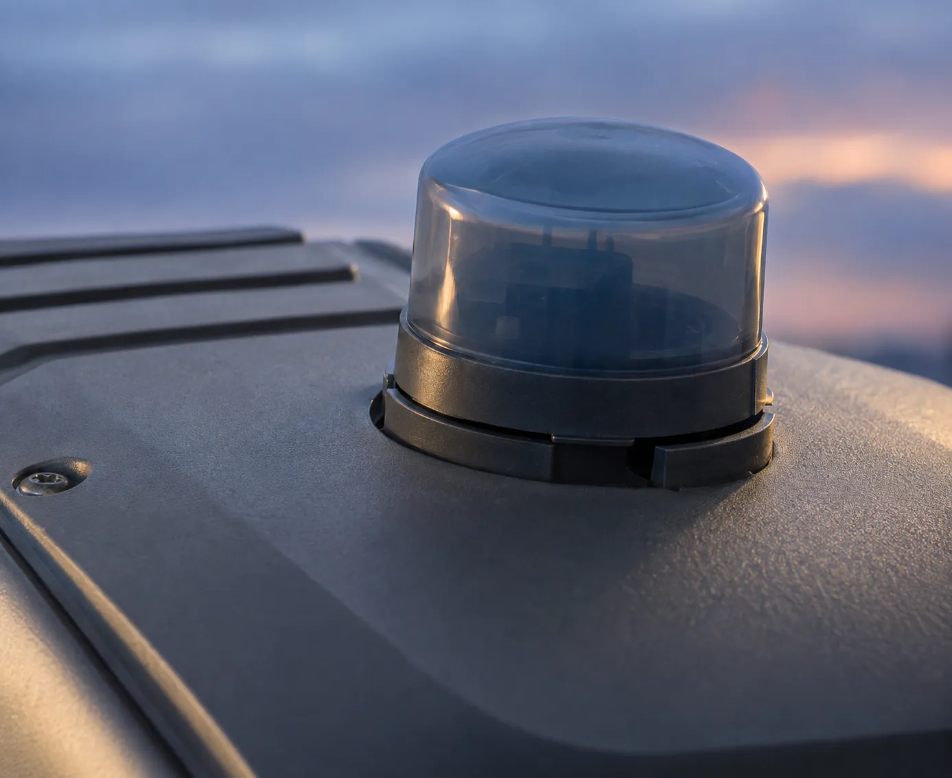
Nobody switches on a street light by hand. Nearly every street light you see is automatic, and the switch lives on the lamp itself. The most common device is a small light sensor called a photocell, mounted on top of the lamp head. When daylight fades past a set point, the photocell closes a switch and the lamp comes on. At dawn it does the reverse.
That is the whole basic loop for most modern lights. Some older districts still run on a different logic: one sensor or one timer drives an entire circuit, so a whole street brightens at the same second. That design saves money on hardware and creates its own failure pattern, which we will come back to.
One quick clarification, because search results mix them up constantly: this article is about street lights, the luminaires that light roads and paths. Traffic lights are a different system. They run on timers and vehicle detection, and flashing your headlights at them does nothing.
Why does one town switch its lights one pole at a time while the next city runs half a district from a cabinet? The answer is ownership. Utilities, municipal departments, and private owners each picked their control habits decades ago, and those habits stick. The hardware has changed around them, from handwritten switch schedules to networked platforms, but the underlying question has never changed: what signal tells the light to turn on?
The Five Signals That Trigger a Street Light
Every control method on the market is an answer to that question, and there are five answers in common use.
The photocell is the workhorse. Its sensing element changes electrical resistance as ambient light rises and falls, and a small circuit translates that into a switch action (HowStuffWorks, 2024). A detail most explanations skip: the turn-on point and the turn-off point are deliberately set apart. The lamp switches on in the evening at a darker reading than the one that switches it off in the morning. That gap, called hysteresis, stops the light from chattering on and off at dusk (Hyperlite, 2025). It also explains a common complaint. A sensor shaded by tree cover, smeared with dust, or faced the wrong way reads the world wrong and fires at the wrong time.
Timers are the second signal: a clock simply opens and closes the circuit at scheduled times. They are cheap and predictable, but a fixed schedule never follows the sunset. Without seasonal adjustment, a timer-controlled street runs late in winter and wasteful in summer. The astronomical timer, or astro clock, fixes this. It knows the installation’s latitude and longitude, computes local sunset and sunrise for every date, and adjusts itself without anyone touching it. Many cabinets run a photocell and a clock together so a blocked sensor or a power glitch cannot leave a street dark.
The last two signals are newer. Motion triggers, usually PIR or radar sensors, keep a lamp dim or off until a pedestrian or vehicle passes, then bring it to full output. They suit low-traffic paths, parks, and courtyards, not arterial roads that must stay lit for safety. The fifth signal is different in kind. Remote commands arrive over a network from a management platform, and they turn a fleet of separate lamps into addressable devices. That layer gets its own section below.
Five trigger signals at a glance
| Trigger signal | How it decides | Best fit | Failure boundary |
|---|---|---|---|
| Photocell (most common) | Reads ambient light through a sensing element; on at dusk, off at dawn | Per-pole control on most modern streets | Shaded, dirty, or mis-aimed sensor fires at wrong times; clean it and check aim first |
| Timer | Opens and closes the circuit at fixed clock times | Small private installations, temporary lighting | Fixed schedule ignores seasonal sunset drift |
| Astronomical timer | Computes local sunrise and sunset from latitude, longitude and date | Cabinet-level control, anywhere labor for seasonal resets is scarce | Wrong coordinates mean wrong times; verify them after setup |
| Motion (PIR / radar) | Holds low output, rises when a person or vehicle passes | Parks, paths, low-traffic courtyards | Wrong choice for arterials that must stay lit |
| Remote command / platform | A management system sends on, off and dimming schedules over a network | City-scale and campus-scale fleets | Depends on network coverage and platform terms |
The practical takeaway for anyone maintaining their own lights: when a photocell-controlled lamp misbehaves, check the sensor’s view of the sky before you condemn the sensor. Confirm the sensing window faces the open sky with no new foliage or signage in the way, then clean it, then test the unit.
Where the Switch Lives: Per-Pole, Circuit and Cabinet
Knowing the signal is half the picture. The other half is where that signal acts, and that decision shapes cost, maintenance, and how badly things go when a component fails. There are three arrangements in the field.
Three control topologies compared
| Topology | Where the switch sits | Cost profile | Failure blast radius |
|---|---|---|---|
| Per-pole | A photocell on each lamp head | Highest hardware count, near-zero design work | One lamp |
| Circuit string | One sensor or clock feeds a contactor that switches a whole feeder | Cheapest hardware, needs cable planning | The whole string |
| Control cabinet | A street cabinet with contactors, clock and photocell, manual bypass | Higher upfront cost, pays back on maintenance speed | Everything on the cabinet’s feeders |
One Photocell Per Pole
This is the default on modern North American streets. Each lamp head carries its own photocell, usually plugged into a twist-lock receptacle built into the housing. When one sensor fails, one light misbehaves, and a technician swaps the unit in minutes from a bucket truck. No drawings, no hunting for a cabinet. The tradeoff is part count: every pole is a small device that will eventually fail, so fleets of this type live on planned photocell replacement cycles.
One Photocell, Many Lights
The older and cheaper pattern drives a whole string of lights from one sensor or timer. As one recent explanation on a question-and-answer forum put it, older setups use a single photocell to activate a string of streetlights because it is cheaper. The catch is that if the photocell fails, the whole string follows it (Reddit r/NoStupidQuestions, 2025). The failure pattern is distinctive and easy to recognize: when a shared sensor dies, an entire street goes dark together, or an entire street burns through the day. If lights fail in groups, stop checking lamps and go find the common device.
The Control Cabinet
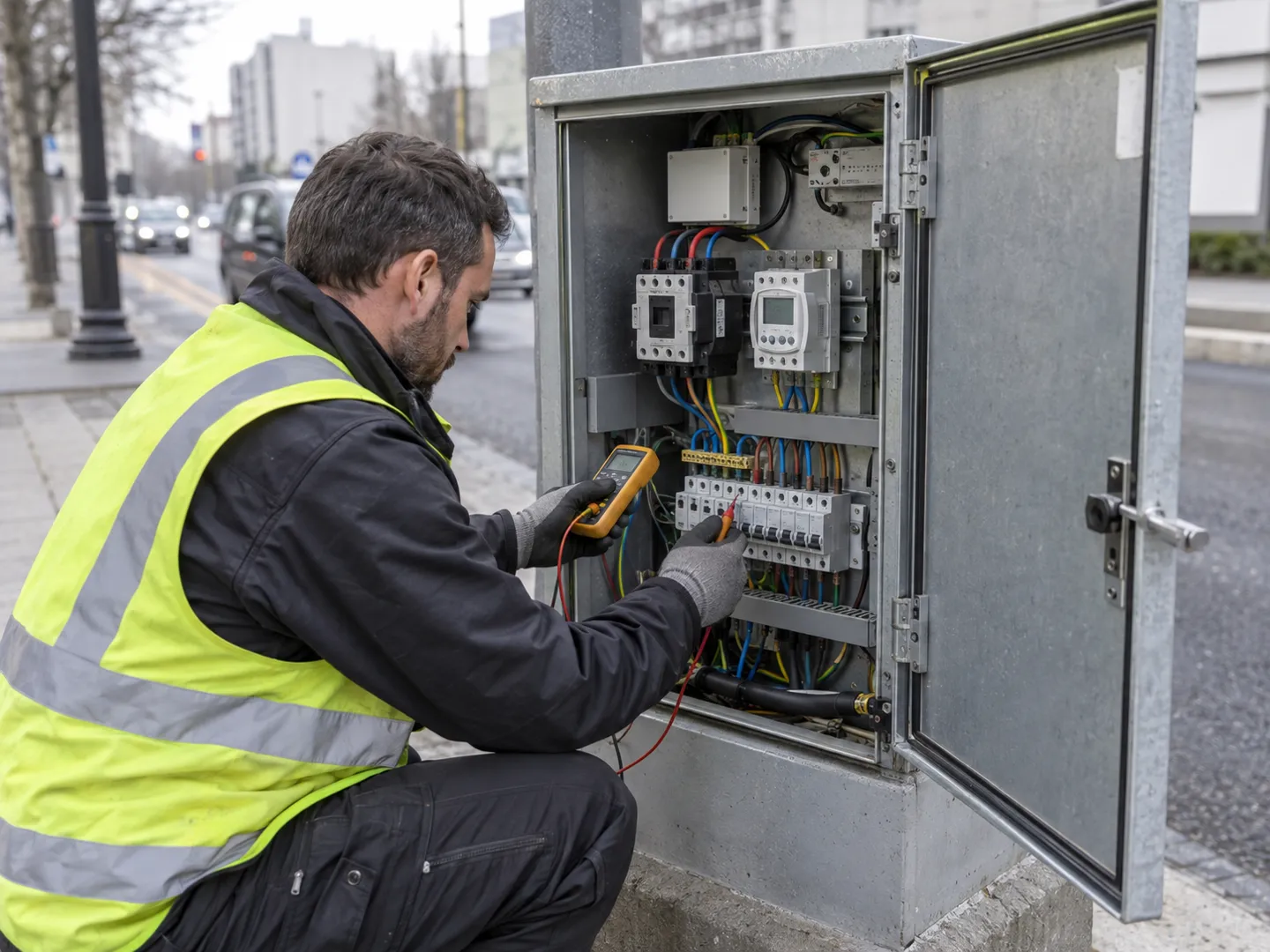
Larger networks concentrate the switching in a street cabinet. Inside sits a contactor that carries the load, a clock or photocell that commands it, and a manual bypass so technicians can force the lights on for testing. The cabinet approach concentrates maintenance in one visitable point and makes group schedules trivial, which is why it remains the municipal norm across much of Europe and Asia. Its cost is in cable and civil work: every light must be fed back to the cabinet’s circuits, so it earns its keep on dense networks, not on a handful of poles.
When Controls Fail: Direction and Diagnosis
A failed photocell can stick in either state. Trade electricians describe both failure directions in the same breath: exterior lights that will not turn on at night, and lights that will not turn off in the morning (ElectricianTalk, 2011). Many photocells are designed with a safety bias: when the sensor itself gives up, the lamp is driven to stay on rather than go dark. The theory is that unlit streets at night are the more dangerous failure. A UK electrician documented exactly this after swapping a suspect unit: the faulty photocell was holding the light on constantly as a fail-safe, and a replacement cured it (ElectricianForum.co.uk, 2010).
That behavior leads to the most misread symptom in this trade. A street light burning at noon looks like a lamp fault, but it is often the control doing its last job.
A street light that stays on all day is usually not a broken lamp. On fail-safe designs, that is what a failed photocell looks like. Before replacing lamps or drivers, test the control: cover the sensor to simulate night, expose it to simulate day, and watch the lamp answer.
Diagnosis has a natural order, and it runs from cheapest to most invasive. Cover the sensor and watch for the lamp to come on. Expose it and watch for the lamp to drop out. If the lamp ignores both tests, bypass the sensor by joining the line and load leads. It is the trade’s routine proof: if the lights come on with the sensor shorted, the sensor took the circuit down with it (ElectricianTalk, 2011). On three-wire units, the red lead is the switched load and black is line, so metering across those terminals tells you whether the sensor is passing power (Reddit r/electrical, 2025). Only then move to the circuit itself: verify voltage at the feeder and open the cabinet if the string runs from one.
The discipline matters because the shortcut fails publicly. One forum electrician replaced the photocell three times on a stubborn installation before finding the real cause elsewhere in the circuit, with voltage and wiring apparently correct on every visit (ECN Electrical Forums). Repeated part-swapping is not diagnosis. Each test above eliminates half the system in one visit.
Matching the Control Setup to the Project
If you own or manage lights rather than maintain them, the question changes from “how does it work” to “which arrangement fits my site”. Three variables decide it: how many poles you have, who maintains them and how often, and whether you expect to add monitoring or dimming later.
Boundary matrix: control setup by scenario
| Scenario | Recommended setup | Where it breaks | Verify before you commit |
|---|---|---|---|
| Private yard or driveway (1–5 poles) | Per-pole photocells | Sensor shaded by new structures or trees misfires | Sensor has clear sky view; wiring is correct (line/black, load/red) |
| Small site: parking, campus, park (10–50 poles) | Per-pole, or one cabinet if poles cluster | Scatter-mounted photocells drift out of sync and upkeep adds up | Maintenance budget exists; adding one spare photocell per 20 poles |
| Town street network (100+ poles, dense) | Cabinet with astro clock, photocell backup | Cabinet pays only if most poles can be fed back without long cable runs | Civil work for feeder cables is costed; bypass switch present for testing |
| Arterial road, safety-critical | Cabinet or per-pole with dimming schedules, not motion-dimming | Motion-held dimming is unacceptable where continuous output is required | Lighting class requires continuous output; fail-safe direction is ON |
| Off-grid road or community, no reliable grid | Solar street lights with built-in controller | Winter energy autonomy limits continuous high output | Local winter insolation data checked against lamp autonomy |
The economics behind that table are shifting, and it helps to read the numbers with their conditions attached. Upgrading old lamps to LED alone typically delivers on the order of 50% energy savings (T&D World, 2025). Adding networked controls on top is what pushes combined reductions to the 60–80% range for cities and utilities (MiNextCities, 2022). Motion-based dimming schemes alone are credited with 50–70% lighting-bill reductions in the right traffic profile (Global Infrastructure Hub, 2020). Vendor proposals that quote a single big number usually blend the lamp upgrade and the control layer. Ask them to separate the two, because they pay back on different schedules, and one of them locks you in for years.
Networked Control: Receptacles, Protocols and CMS
The third layer of control turns a fleet of autonomous lamps into one addressable system. Physically it is three stacks: a controller on each lamp, a network underneath, and a management platform on top. Get the first stack wrong and the other two become expensive to fix.
The Luminaire-Side Interface
Every networked scheme starts with a socket on the lamp. In North America the dominant interface is the NEMA twist-lock receptacle standardized under ANSI C136.41, which added dimming contacts to the older photocell receptacle format (TE Connectivity, 2013). The pin count is the capability statement. A 3-pin unit under the earlier ANSI C136.10 standard switches on and off only. A 5-pin receptacle to ANSI C136.41 adds two contacts carrying a 0–10V dimming signal. A 7-pin unit adds further auxiliary contacts for extra control channels (LED Lighting Expert, 2021). Products on the market, from simple photocontrols to full networked controllers, plug into these receptacles interchangeably (Intermatic).
Europe converged on a different answer: the Zhaga Book 18 interface. Introduced in 2018, it defines a compact socket for plug-in control modules and carries power and data over the same connection (Tvilight). The practical meaning for a buyer is the same on both sides of the Atlantic. The receptacle you specify today decides whether tomorrow’s controller is a two-minute unplugged swap or a rewiring job. Specify the pin count and dimming contacts before you shortlist fixtures, not after.
Receptacle options and what they commit you to
| Interface | Contacts | What it carries | Decide it when |
|---|---|---|---|
| NEMA 3-pin (ANSI C136.10) | 3 | On/off switching only | Your control plan is pure photocell switching |
| NEMA 5-pin (ANSI C136.41) | 5 | Switching plus 0–10V dimming | You want scheduled dimming later without rewiring |
| NEMA 7-pin (ANSI C136.41) | 7 | Switching, dimming, auxiliary channels | You expect sensor or monitoring add-ons |
| Zhaga Book 18 | Multi-pin compact socket | Low-voltage power plus data (DALI-2/D4i class) | Your market follows the European controller ecosystem |
Networks and the Platform
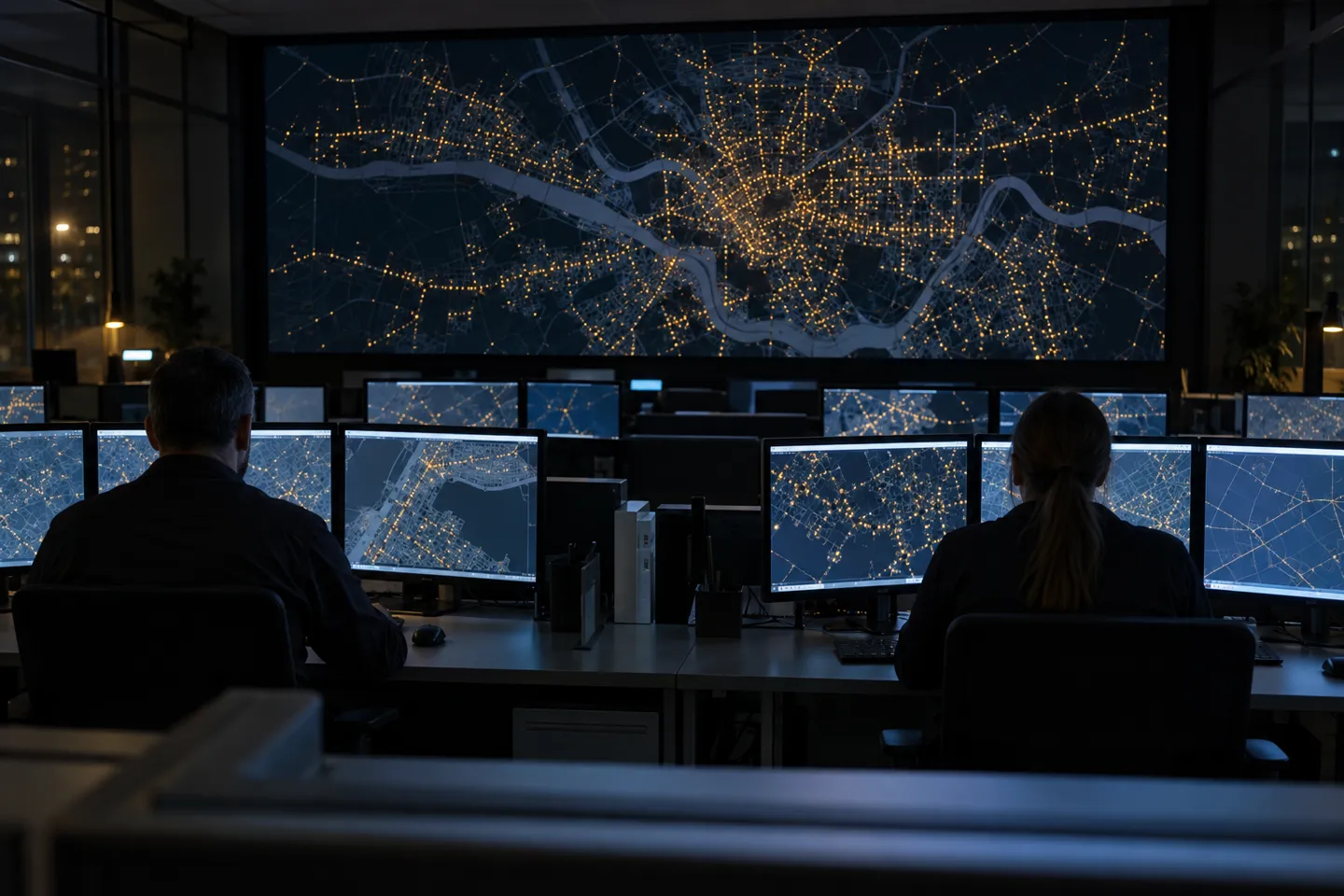
A networked controller rides that receptacle and talks to the platform over a wide-area link: LoRaWAN, NB-IoT, or power-line communication on the existing feeders. The platform, called a central management system or CMS, does the visible work. It shows which lamps are on, flags failures automatically, runs dimming schedules by zone, and meters energy per pole. A CMS is substantial enough to be its own procurement: one London borough awarded its street lighting CMS contract through a dedicated cabinet-level approval process (Haringey Council, 2021).
That is also where the long-term risk sits. As one smart-city procurement guide puts it, the controller, network protocol, and CMS a city selects today will govern every fixture-level command, fault report, and energy read for the useful life of the LED fleet (Oxmaint, 2026). Its reasoning is blunt: the switching cost after year three is high enough that most cities never revisit the choice. Open protocols and standard receptacles are the only portable insurance. A proprietary platform with a custom controller format can be cheaper on day one and irreplaceable on day one thousand.
The 15-year lock-in
15 years
The commitment hiding inside a smart lighting tender: after year 3, switching cost is so high that most cities never revisit their controller, protocol and CMS choice.
The receptacle standard and protocol clause you write on day one outlive every fixture you buy.
The Off-Grid Parallel: How Solar Street Lights Control Themselves
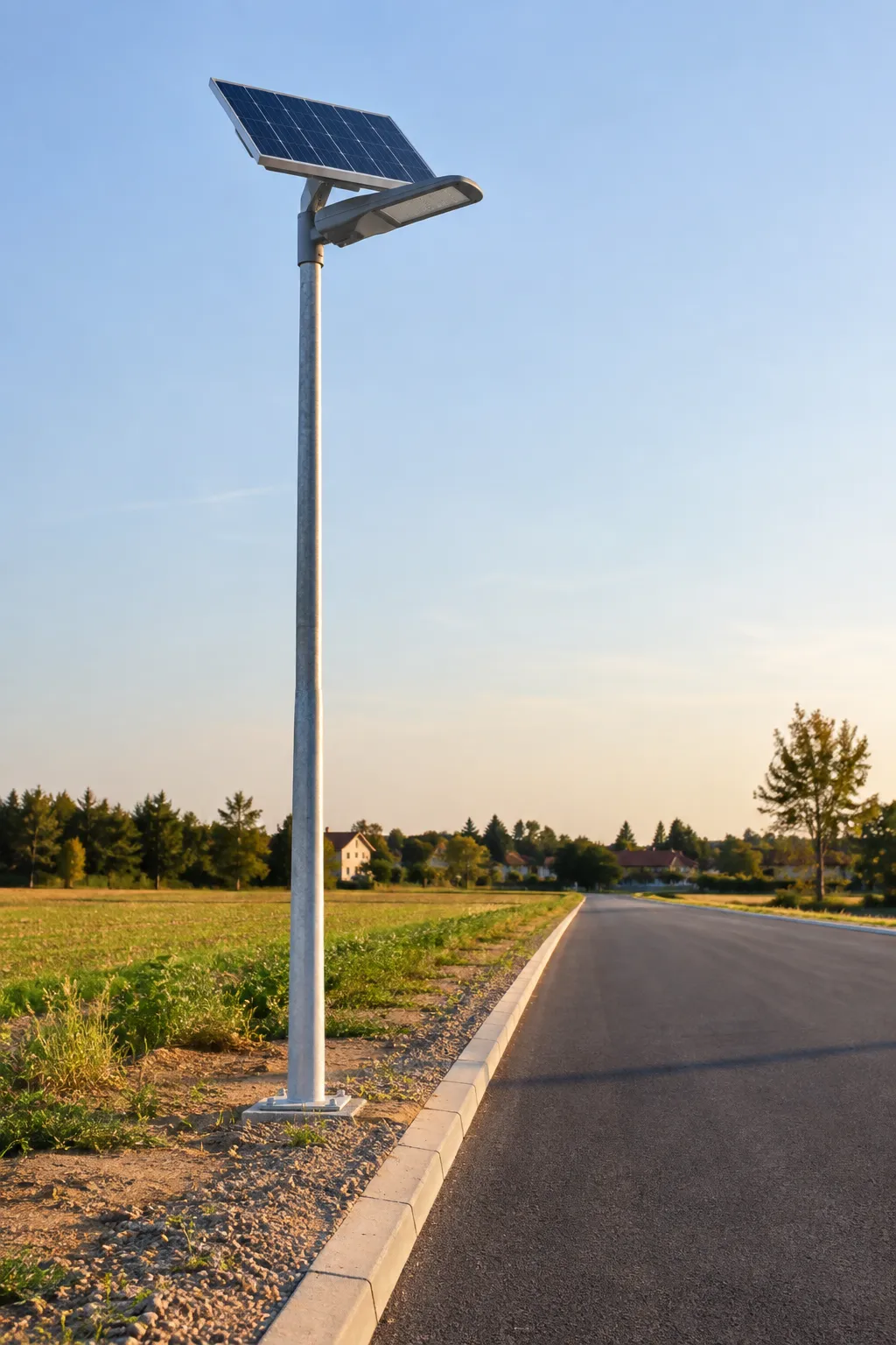
Solar street lights solve control with a different architecture: there is no circuit and no cabinet, because each pole is its own grid. A charge controller manages the panel, battery and lamp, and the control logic ships factory-set. The standard scheme combines light control with time control. The lamp wakes at dusk, then runs a programmed profile, such as full output for the first hours and reduced output toward dawn, to budget the battery through the night. Typical specifications across the category include IP65 sealing, a -20 to 50°C operating window, and 25,000 to 50,000 hour LED life. Remote controls and motion sensors are common options, adding manual override and presence-based dimming to the same controller.
The boundary is energy, not intelligence. A solar lamp cannot be commanded past what its battery stored that day, so on safety-critical arterials that require continuous full output, autonomy in a bad winter week is the deciding calculation. The checkable step: demand the vendor’s autonomy estimate computed against local winter insolation data for your actual site, not against a generic sunbelt profile. Where that calculation passes, the off-grid route deletes the cabinet, the feeder cables, and the trenching crew from your budget entirely.
What This Means for Your Next Bid
Everything above collapses into an ordering rule for tender documents: control requirements come before fixture requirements. Write the receptacle standard and pin count, the dimming protocol and its openness, and the controller replacement terms into the specification first. Only then admit fixture brands, and require every bidder to meet the control clauses rather than negotiate them away line by line.
Put the control behavior into acceptance too, because it is testable in minutes per pole. Cover the photocell: the lamp must come on. Expose it: the lamp must drop out. Ask the supplier in writing which way their control fails, and on fail-safe designs confirm the failure state is lights-on, not lights-off. A fleet that ships with an unverified failure direction hands you a midnight discovery instead of a punch-list item.
And budget by architecture, not by habit. On roads without reliable grid or with costly trenching, that money belongs in the solar line instead. The condition is the winter autonomy calculation above. The four questions below work on any supplier, which is the point of specifying interfaces first.
Supplier questionnaire for street light controls
- 1Which receptacle standard and pin count do you support (NEMA 3/5/7-pin, Zhaga Book 18)?
- 2Is the dimming protocol open (0–10V, DALI/D4i) or proprietary?
- 3Can the control module be replaced without rewiring the luminaire, including out of warranty?
- 4For solar units: show the autonomy calculation against local winter insolation, with light-control and time-control profiles in writing.
If you are assembling these requirements into a tender, WOSEN builds grid-tied and solar street lights that are dimmable as standard, and our customization program covers the rest of the spec down to 15°–120° optics, private molds and your own branding.
Start Your Street Light Quote
Send WOSEN your pole count, target lighting class and control requirements — grid-tied or solar, you get a configuration and quotation written to your control clauses.
Request a QuoteReferences
- HowStuffWorks. “How do the streetlights turn on automatically at night?” 2024. https://science.howstuffworks.com/environmental/energy/question363.htm
- Hyperlite. “Fixing a Photocell That Cycles On and Off Repeatedly.” 2025. https://hi-hyperlite.com/blogs/comprehensive-guides/photocell-cycling-fix-outdoor-lights
- Reddit r/NoStupidQuestions. “Do streetlights all have a light sensor on them?” 2025. https://www.reddit.com/r/NoStupidQuestions/comments/1oeclv1/do_streetlights_all_have_a_light_sensor_on_them
- ElectricianTalk. “Photocell failure question.” 2011. https://www.electriciantalk.com/threads/photocell-failure-question.20897
- ElectricianForum.co.uk. “Photocell light staying on all day.” 2010. https://electricianforum.co.uk/threads/photocell-light-staying-on-all-day.10429
- Reddit r/electrical. “Photocell sensor is always on.” 2025. https://www.reddit.com/r/electrical/comments/1l914dv/photocell_sensor_is_always_on
- ECN Electrical Forums. “Photo cell staying on.” https://www.electrical-contractor.net/forums/ubbthreads.php/ubb/printthread/Board/1/main/5731/type/thread.html
- T&D World. “Smart streetlights: The backbone of tomorrow’s sustainable cities.” 2025. https://www.tdworld.com/smart-utility/article/55267119/smart-streetlights-the-backbone-of-tomorrows-sustainable-cities
- MiNextCities. “The Benefits of LED & Smart Street Lighting.” 2022. https://minextcities.org/wp-content/uploads/2022/11/The-Benefits-of-LED-and-Smart-Street-Lighting.pdf
- Global Infrastructure Hub. “Smart Street Lighting for Energy Efficiency.” 2020. https://www.gihub.org/infrastructure-technology-use-cases/case-studies/smart-street-lighting-for-energy-efficiency
- TE Connectivity. “Lumawise Endurance N Rotatable Dimming Receptacle (ANSI C136.41).” 2013. https://www.te.com/content/dam/te-com/documents/appliances/global/lumawise-endurance-n-rotatable-dimming-receptacle.pdf
- LED Lighting Expert. “Photocell receptacles: 3, 5, or 7 pin? NEMA standards.” 2021. https://www.ledlightexpert.com/photocell-receptacles-3-5-or-7-pin-nema
- Intermatic. “K171H Locking Type Photocontrol Receptacle.” https://www.intermatic.com/Product/K171H
- Tvilight. “Zhaga D4i – a de facto standard for smart street lights.” https://tvilight.com/zhaga-d4i_a-de-facto-standard-for-smart-street-lights
- Haringey Council. “Street Lighting CMS Cabinet Report.” 2021. https://www.minutes.haringey.gov.uk/documents/s122600/Street%20Lighting%20CMS%20Cabinet%20Report%20-FINAL.pdf
- Oxmaint. “Street Light Vendor RFP Software: Smart City Selection Guide.” 2026. https://oxmaint.com/industries/government/street-light-vendor-rfp-software-smart-city-selection-guide
- WOSEN. “Series LUMINA Adjustable LED Street Lights.” https://www.wosenled.com/portfolio/series-lumina-adjustable-led-street-lights/
- WOSEN. “Customization.” https://www.wosenled.com/customization/
- WOSEN. Homepage. https://www.wosenled.com/

 English
  Spanish
  French
  German
  Italian
  Arabic
  Russian
  Portuguese
  Dutch
Dutch  Indonesian
  Turkish
  Polish