Introduction: Illuminate Your World Automatically
Envision a reality: the world outside is well-lit; lights come on at the appropriate times and turn off in accordance with day or night—all done with no manual labor needed. This is not futuristic thinking, and it’s not too far off into the future; it’s the truth with automatic street lights. Apart from providing security in your backyard, smart street light systems can also help save energy during light hours in small community pathways. Wearing the hat of a builder or a DIY enthusiast, you are likely to enjoy setting up your automatic street light control system to learn the basics of electronics, sensor-based technology, and control automation. This is a journey that not only helps brighten a space, but also your mind on the workings of the street lighting systems.
This guide aligns with your DIY passions, detailing how to transform your street lights into intelligent illuminators. Or, if you are a student working on a school project, this guide will serve as the foundation of the more advanced concepts. You will learn the basic principles and the necessary components, then work through the practical steps of construction. We’ll continue to explore advanced possibilities and discuss real-life aspects of your street light system.
Essential Components for Your Automatic Street Light
In order to make automatic street lights, there are some basic electronic parts that work together in the unit to illuminate the street and sense the light level. It is therefore vital to appreciate them:
- Light Sensor (e.g., Light Dependent Resistor – LDR): This serves as the “eye” of the system. An LDR’s electrical resistance changes depending on the intensity of light incident on it. While LDRs are a favorite for hobbyists for their low price and ease of use, there are more sophisticated alternatives like photodiodes or phototransistors, which have differing properties.
- Controller/Switch (e.g., Transistor or Microcontroller): This is the “brain” component; it gets information from the light LDR and controls the light source.
- Transistor (like BC547): In basic circuits, a transistor serves as an automatic switch. In other circuits, he goes to evoke depending on the light falling on the LDR circuit, which will decide whether the order to illuminate will be sent to the light bulb through the capacitor or not.
- Microcontroller (like Arduino, ESP32): With a programmable microcontroller, more advanced projects can be done since it can read sensor data, process it based on specific thresholds and timings, and control the light source via digital outputs. With such logic, more complex tasks can be performed.
- Light Source (e.g., Light Emitting Diode – LED): LEDs are most preferable for light DIY projects since they are energy efficient, durable, and small. If you wish to simulate streetlight mounting brighter illumination, you can use several standard LEDs, high-power LEDs, or small LED modules that require supportive driving circuitry.
- Other Necessary Components:
- Resistors: Needed in interfacing the sensors, controlling the current and voltage to ensure levels needed within the circuit, as well as for the LEDs, and protecting the electronic components.
- Transformer: For those whose projects involve changing AC power into DC voltage for the different components of the circuit.
- Power Source: Gives off electrical energy, which can come from Batteries like 9 Volts for small portable projects, while DC power adapters of 12V and 24V are also applicable. Other sources include integrated solar panels and batteries for off-grid operation.
- Connecting Materials: The components require wires, breadboards for prototyping, or perfboards/PCBs for building more permanent constructions.
- Relays/Power Transistors: A relay or a more powerful power transistor (such as MOSFET) will serve as an intermediary switch if controlling a light source that requires higher voltage or current than the primary control circuit can manage.
The choice of components will vary depending on the complexity of the project, the required light output, and the available power source. The simplest design could consist of an LDR, several resistors, a transistor, and an LED, all powered by a small battery. In contrast, the more powerful, fuller-featured version will involve a microcontroller with more advanced LEDs and a more substantial power supply.
Benefits of Implementing Automatic Street Lights in Your Community
Implementing automatic street lights, even on a small scale, offers significant advantages:
- Enhanced Energy Efficiency: Automatic lights that have light sensors tend to only turn the lights on from dusk till dawn. LED automated systems will provide greater energy savings of between 30% to over 70% when compared to traditional systems or lights set on timers.
- Lower Operating Costs: A reduction in the community’s overall energy consumption is directly linked to a reduction in the community’s electricity cost. The savings resulting from reduced energy use can be redirected towards other significant community programs.
- Reduced Maintenance & Extended Lifespan: Lighting is enabled only when needed, which further reduces operational hour accumulation. This is particularly beneficial for LEDs with a 50,000-hour rating as their replacement is less frequent, extending service life and lowering associated labor costs. Automation also eliminates the effort needed for manual switching.
- Improved Safety and Security: Providing controlled lighting on pathways after dark eliminates chances of accidents and many crimes, improving safety for residents.
- Environmental Responsibility: Increased safety, environmental sustainability, and conserves energy by using sophisticated automated lighting, which decreases the overall carbon footprint.
Building a Basic LDR Circuit Automatic Street Light Project
Now, let’s explore the simplest case: a street light built with an LDR and a transistor. At this stage, the goal is to build a project that demonstrates simple electronic circuits controlled by light levels, as an introduction to basic electronics.
The core goal is to design a circuit in which the light-dependent resistance (LDR) controls the base current of the transistor, and the transistor drives the LED as a switch. In darkness, the LDR’s resistance is high. This allows some current to flow into the transistor’s base, which turns it on. This illuminates the lamp. Under light, the resistance of the LDR is low, which means the current will be diverted away from the base, so the transistor will turn off and the light lamp will be extinguished.
Step 1: Setting Up the Light Dependent Resistor (LDR)
The LDR must be connected to a circuit that will translate its change in resistance value into a corresponding change in some voltage. The easiest way to accomplish this is to use the LDR with a fixed resistor in a simple voltage divider circuit configuration. Attach one terminal of the LDR to the positive voltage supply (e.g., positive terminal of battery) and the other terminal to one terminal of a resistor (which we will name R1 and of value between 10kΩ to 100kΩ). R1’s other terminal is connected to a negative voltage supply (ground). The voltage at the junction between LDR and R1 will change depending on the light intensity. In a strongly lit environment, the voltage at the junction will be low because the LDR resistance is low. In darkness, LDR resistance is high, and so the voltage at the junction will be higher. This voltage will control the transistor.
Positioning the LDR is very important. It must be located in a position where the surrounding light can be detected. Best position LDR looking upward towards the sky, but must be protected from the LED light that it controls. If the LED light strikes the LDR, it will cause flickering problems. Light will turn on, LDR will sense it, turn the light off, LDR will sense darkness, turn the light on, and this cycle will continue.
Step 2: Wiring the Circuit for Automation
Take the output voltage from the surface of your voltage divider (the joining point of LDR and R1) and connect it to the base of the NPN transistor (for instance, BC547) via another resistor (which we shall denote as R2 and is usually around 1kΩ). This resistor ensures that the current entering the base of the transistor is limited. The emitter of the NPN transistor has to be connected to the negative terminal of your power supply (commonly referred to as ground).
Power supply positive terminal should be connected to the LED (through the positive leg, the anode, with a current limiting resistor R3, usually 330Ω for a standard 5mm LED powered by 9V). The cathode, which is the negative leg of the LED, connects to the collector of the NPN transistor.
Here’s a simplified flow of how it works:
- Daylight: High light intensity -> Low LDR resistance -> Low voltage at the junction of LDR and R1 -> Insufficient base current for the transistor -> Transistor is OFF -> No current flows through the LED -> LED is OFF.
- Darkness: Low light intensity -> High LDR resistance -> High voltage at the junction of LDR and R1 -> Sufficient base current for the transistor -> Transistor is ON -> Current flows through the LED -> LED is ON.
While prototyping on a breadboard or soldering components on a perfboard or PCB, ensure that all connections are secured. Do not apply power until the LED and the transistor’s pinout(Base, Collector, Emitter) are confirmed to be plugged in the correct polarity. During wiring, a visual aid of a basic circuit diagram can be extremely helpful and is easily accessible online.
Advanced Control with Arduino
In charge of basic automated systems, the LDR and transistor pair are rather simple and efficient. The addition of microcontrollers such as the Arduino Uno or ESP32 opens avenues for much more complex designs. An LDR can be read by an Arduino, which can then control (via digital outputs) an LED or powerful light through a relay after processing the data.
With Arduinos, the most relevant feature to consider is programmability. Instead of depending on the thresholds set by a device’s components, one can define in the code the exact values that would turn the light on and off. Hysteresis can be incorporated with ease, time delays can be set, and much more rational and intricate conditions can be fulfilled.
In order to create this version, you will require: an Arduino board, a power source for the Arduino, an LED with a current limiting resistor, a 10 kΩ resistor, and connection wires.
As before, connect the LDR and the resistor to form a voltage divider. The junction of the LDR and resistor is to be connected to one of the analog inputs of the Arduino (for example, A0). The LED and its resistor are connected to one of the digital outputs of the Arduino (for example, pin 9 or 10 if PWM will be used for dimming, otherwise any digital pin like 7 or 8 will do).
The Arduino code will involve:
- Reading the analog value from the LDR input pin (0-1023). This value will be between 0 and 1023 (for a 10-bit ADC).
- Mapping this analog value to a light level. A higher value from the voltage divider means less light on the LDR.
- Setting a threshold value. When the LDR reading crosses this threshold (indicating darkness), turn the LED output pin HIGH. When it crosses another threshold (indicating sufficient light), turn the LED output pin LOW. Using slightly different thresholds for ON and OFF helps prevent flickering when light levels are near the switching point.
- Optionally, using Pulse Width Modulation (PWM) on a compatible digital pin (0-255) to control the brightness of the LED, allowing for dimming.
The microcontroller’s versatility allows for straightforward modification. For instance, time-based control (e.g., dimming late at night) can be implemented with the addition of a real-time clock (RTC) module, and further energy saving features can be implemented by integrating additional sensors, such as Passive Infrared (PIR) or radar sensors that detect motion and only activate or brighten the lights when presence is detected.
-
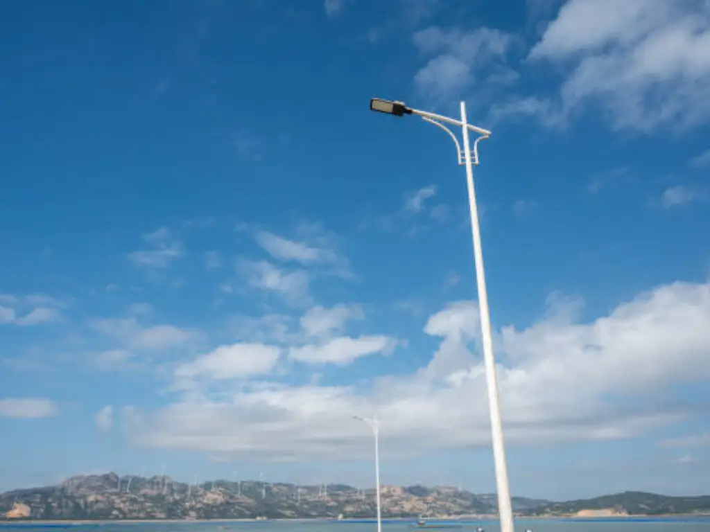
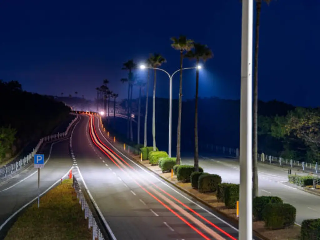
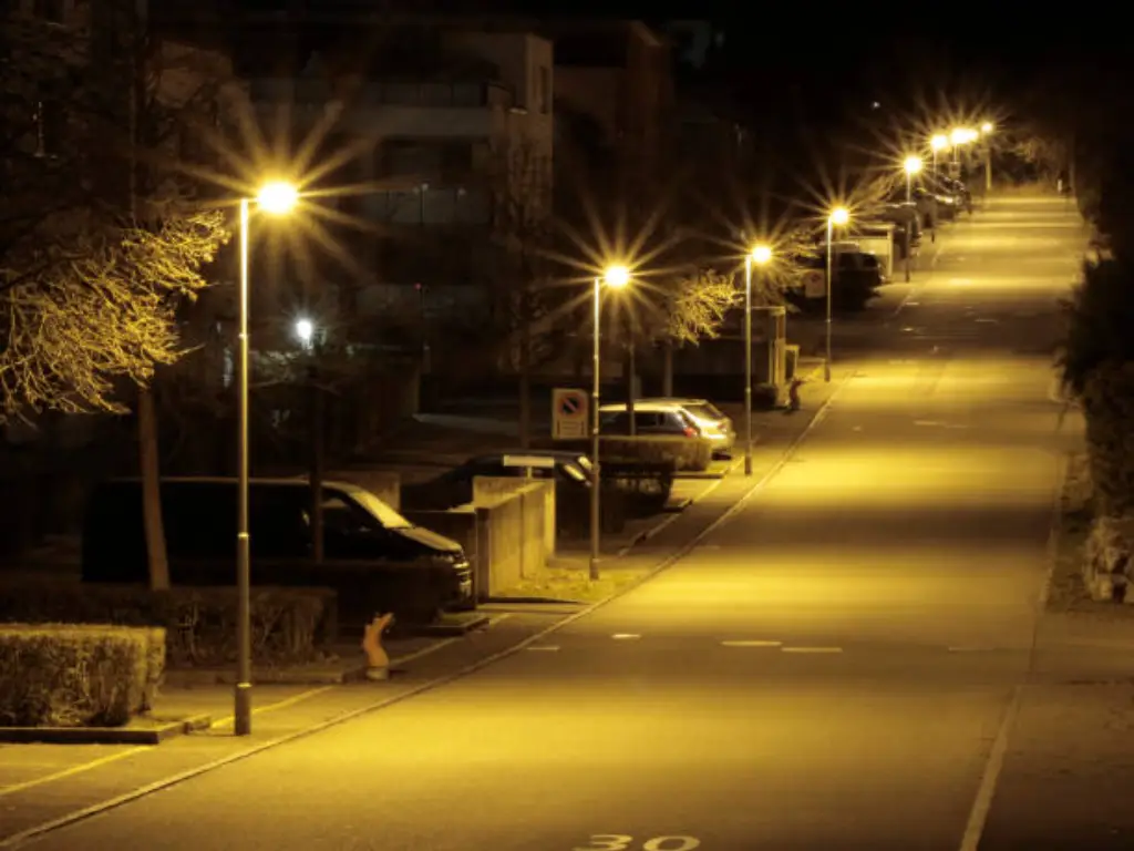
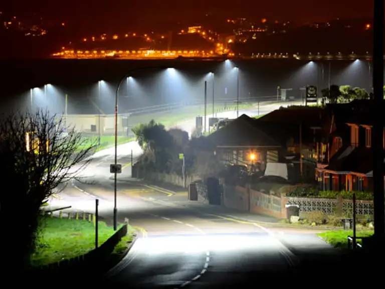 Street Lighting
 -
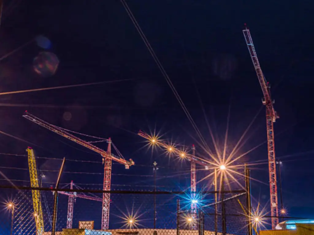
 Stadium Lighting
 -
 Parking Lot Lighting
 -
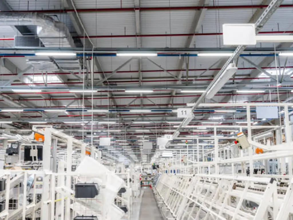
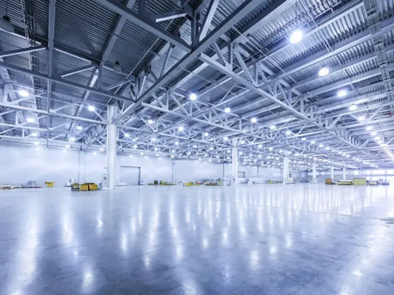 Industrial & Warehouse Lighting
 -
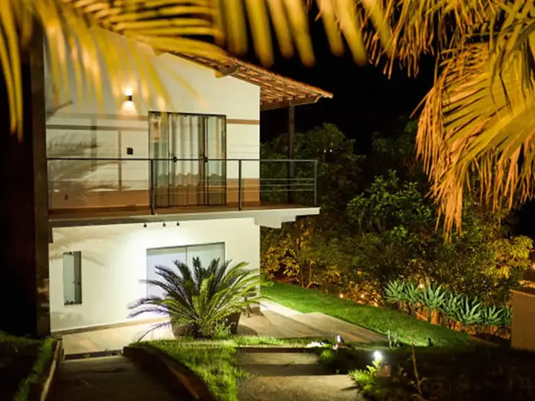 Garden Lighting
 -
 Commercial Lighting
Optimizing Your Project for Real-World Use
Constructing a circuit on a breadboard is helpful as a starting point. However, placing an automatic street light requires additional considerations regarding longevity, functionality, and safety.
Safety and Weatherproofing Tips
All outdoor electrical activities require weather considerations. Components may suffer from rain, humidity, dust, or temperature change, as well as being a safety risk. Shielding your circuit in a weatherproof enclosure box with an IP rating suitable for outdoor use is a must. All electrical connections must be moisture-resistant and protected. If you are using mains power, which is almost never suggested for DIY projects, consult an electrician and take GFCI protective measures.
For low-voltage DC power projects such as battery or DC adapters, the risk is lower; however, safeguarding against shorts and moisture is still important for prolonging equipment life and avoiding damage. Other sensors like LDR should be unobstructed, but the circuit board should be shielded. Silicone sealant can help maintain structural integrity when used around cable entry points.
Energy Efficiency Upgrades
You can do quite a lot besides having the system just switch on and off to save energy.
- LED Selection: Use high-efficacy LEDs. A standard 5mm LED will work for small models, but in real-life street lights, high-power LEDs are used for their efficiency in excess of 150 lumens per watt.
- Dimming: As explained in the Arduino section, adding dimming capability is one of the most powerful optimizations. The light does not need to be at its maximum brightness the entire night. It could dim to a lower level during quiet hours and only brighten upon detecting motion. This further reduces energy consumption by an additional 30-50% beyond simple on/off automation.
- Solar Integration: As an eco-friendly and stand-alone approach, a solar panel, a charge controller, and a rechargeable battery could be added. The solar panel charges the battery during the day, while the battery can power the light at night. This requires precise determination of the solar panel and battery size, alongside the region’s power consumption and solar irradiance, in comparison to the light’s power consumption.
| Lighting Type | Power Consumption (W) | Operating Hours (Avg per night) | Approx. Annual Energy (kWh) | Notes |
| Incandescent (Manual) | 100 | 12 | 438 | High energy use, manual control |
| LED (Manual Timer) | 40 | 12 | 175.2 | Efficient bulb, but fixed timer may waste |
| LED (Basic Automatic) | 40 | 10 (Dusk till Dawn) | 146 | Reduced hours based on light sensor |
| LED (Smart Automated) | 40 (Avg 15W with dimming/motion) | 10 | ~55 – 75 | Adaptive brightness, motion sensing |
Common Challenges and Troubleshooting
Even relatively simple electronic systems can present problems when setting up your system. Here are five typical issues in automatic street light projects and their respective solutions. :
- Light stays on constantly (day and night):
- Possible Cause: LDR circuit does not properly control the transistor/microcontroller input. Setting it too high (for Arduino) or using biased resistors is wrong (for the LDR circuit).
- Troubleshooting: Check the LDR wiring and the output of the voltage divider. Check the voltage at the transistor base/microcontroller input against time. It should move significantly. Modify R1/R2 resistor values per code or threshold set. Guard against the LDR being protected against light.
- Light never turns on:
- Possible Cause: No supply to the circuitry, LED incorrectly connected, LED or transistor damaged, no current due to wrong wiring (current cannot flow), or biasing value has been altered to a lower value.
- Troubleshooting: Confirm connections to the power supply and corresponding voltage values. Confirm correct LED connections, check polarity. Modify all parts if possible with tests. Check all connections as per the diagram meticulously. Change the set threshold in the code and bias check resistors.
- Light flickers or cycles on/off repeatedly near sunrise or sunset:
- Possible Cause: As the LED illuminates, the light striking the LDR may flip around the threshold, keeping the causative LDR oscillating bound to rapid switches around the zero crossing.
- Troubleshooting: Re-position the LDR so they are out of view of the LED’s light. In Arduino code, add hysteresis: different thresholds for turning ON and OFF.
- Sensitivity is too low or too high (light turns on/off at wrong light levels):
- Possible Cause: The fixed resistor value in the voltage divider (R1) is not appropriate for the specific LDR, or the code threshold (for Arduino) needs adjustment.
- Troubleshooting: For LDR/transistor circuit, try different values for R1 (often a potentiometer is used in designs to make this adjustable). For Arduino, adjust the digital threshold value in the code until the light switches at the desired ambient light level.
- Components overheat or drain power quickly:
- Possible Cause: Utilizing unsuited resistors, as too much power is overriding loose container cap transistors, low load transistors are used, or undersized parts/power supply are being used.
- Troubleshooting: Check calculations for all resistors, particularly the series resistor connected with the LED. Make certain the transistor selected is current tolerant for the load. Pick out a current capable Power source.
- Troubleshooting these issues in a project contributes to the development of more sophisticated skills and requires more problem-solving capabilities.
Can this project be scaled for larger communities?
It is a remarkable educational opportunity while building your own automatic street light project, whether a simple circuit or a sophisticated Arduino-based system. It instills the basics of electronics, programming logic, and automation principles. It can be created for private use, for educational exercises, or to illuminate a small area of a garden path and a porch, among other places.
Thinking of putting an automated street lighting system on an entire street, a park, a large campus, or in a commercial complex shifts your DIY mindset towards the more critical parts of the implementation.
Manual scaling of dozens or even hundreds of individually crafted units poses serious problems as the complexity of the system increases beyond your personal DIY capabilities:
- Consistency and Reliability: While in terms of performing identically, all units share similar outcomes in a diverse environment, with the manual assembly and mixed components, performance consistency greatly boils down to environmental conditions.
- Installation and Maintenance: With all aspects combined, installing units with individual crafts causes a complex, never-ending labyrinth, trying to maintain centralized control, lacking checkpoints for remote monitoring, further expediting troubleshooting.
- Robustness and Longevity: Harsh weather conditions, open-air conditions call for a complete lack of uncertainty along with tested components as well as waterproofing and strength for the structure to endure years and decades while being exposed to the elements. All part of needing industrial-grade components, which DIY projects often lack.
- Advanced Features Integration: The implementation of proactive smart features like predictive maintenance, integration with city-wide smart grids, and traffic flow adaptive smart dimming requires advanced systems and corresponding communication protocols, which go beyond normal diy projects.
- Warranty and Support: Support and warranty services are not available for do-it-yourself projects. Professional services for repairs or replacements are the sole responsibility of the individual.
When to Consider a Professional Solution
When your needs span larger areas or whole communities and go beyond a single project, the limitations of DIY solutions become apparent. This is the stage when a scaled, reliable automatic street light system professionally crafted to address your needs becomes a necessity. Just like WOSEN, a specialized manufacturer, offers distinct benefits for professional lighting solutions tailored for significant deployments:
- Built for Reliability and Longevity: Unlike hobbyist builds, professional LED street lights are constructed with high-quality materials and are robustly engineered, ensuring 50,000 hours of service life, high weatherproof ratings (IP66), and resiliency against extreme outdoor conditions. Coupled with hefty 5-7 year warranty periods, these claims provide invaluable trust and assurance.
- Sophisticated Sensory Features: From simple light presence detection, the professional grade goes way beyond that. Motion detection is enabled by specialized radar and human sensors built into the fixtures, enabling adaptive dimming that vastly improves energy efficiency and security.
- Effortless Centralized Control and Tiered Scalability: Managing a lot of DIY lights can easily turn into a logistical nightmare. Professional-grade solutions have intelligent terminal operations and integrated LoRa mesh technology for stable communication that allows control, management, and monitoring of an entire network from a single access point.
- Unwavering Standards and Yield Output: Consistent performance across all units is needed during Scaling. Companies like WOSEN have noted the ability to consistently produce with accuracy up to 300,000 units monthly, which is a stark contrast to the variability of individual DIY builds. WOSEN also ensures uniform high quality required for large-scale projects.
By choosing a professional solution, you are ensuring an investment in reliability, advanced features, and scaling that come with complexities when automating lighting at a community level.
Conclusion: The Future of Automated Street Lighting
Creating your very own automated model of the street light gives you an insight into the world of sensors, circuits, and automation. From the basic LDR and transistor circuits to the more advanced programmable Arduino-controlled systems, you obtain skills that will give you an appreciation of how technology enhances and makes environments run smoother.
Essential parts have been discussed, a basic model was built, the potential of microcontrollers was described, important optimizations such as weatherproofing and energy efficiency were covered, and common troubleshooting was explained. The steps of creating the automated street light model are endless and can most certainly assist with learning, however, there is a limit when it comes to scaling.
The way street lamps function today is predictable, but the integration of new technologies creates opportunities for autonomous and smart features. Basic dusk-till-dawn switches, street lamps equipped with light sensors that adjust their levels based on the traffic, advanced smart city frameworks, and many more systems all benefit communities and citizens by contributing towards improved safety, sustainability, and livability. Whether you further pursue advanced DIY challenges, tackle larger professional answers, these principles of automatic illumination will always be useful until the time comes when a more advanced smart environment needs to be built.